Network of Scientific Journals from Latin America and the Caribbean, Spain and Portugal
Artículos de Investigación Aplicada
Eccentrically-compressed reinforced concrete columns strengthened with partial jacketing
Pilares de concreto armado reforçados à flexo-compressão com encamisamento parcial
Columnas de hormigón armado comprimido de forma excéntrica y reforzados con encamisado parcial
Eccentrically-compressed reinforced concrete columns strengthened with partial jacketing
Revista de la Asociación Latinoamericana de Control de Calidad, Patología y Recuperación de la Construcción, vol. 8, no. 2, 2018
Asociación Latinoamericana de Control de Calidad, Patología y Recuperación de la Construcción, A. C.
Received: 23 October 2017
Accepted: 21 March 2018
Published: 30 April 2018
Abstract: The behavior of six uniaxial compression columns is investigated. Specimen featured an initial section of (120 x 200) mm2, a final section of (200 x 200) mm2 and height of 1.600 mm, strengthened on the tensile and compression sides with plaster or not. Adherence between new and old concrete, and cracking pattern was satisfactory. Although coated columns showed the same behavior to their respective non-coated ones even when concrete area was reduced by approximately 20%, problems consisted in the crushing of the reinforced concrete layer immediately prior to the rupture of the columns. This strengthening proved to be more adequate when undertaken at the columns´ compressed zone and may be executed through conventional procedures with or without mortar coating layer.
Keywords: columns, partial retrofit, partial jacketing, reinforced concrete.
Resumo: Investiga-se o comportamento de seis pilares à flexo-compressão. As amostras apresentaram uma seção inicial de (120 x 200) mm2, uma seção final de (200 x 200) mm2 e altura de 1.600 mm, reforçadas nos lados tracionados e comprimidos com reboco pré-existente ou não. A aderência entre concreto novo e velho, e padrão de fissuração foram satisfatórios. Embora os pilares revestidos tenham o mesmo comportamento dos pilares não revestidos, mesmo quando a área de concreto foi reduzida em aproximadamente 20%, os problemas consistiram no esmagamento da camada de reforço imediatamente antes da ruptura dos pilares. Esse reforço provou ser mais adequado quando realizado na zona comprimida podendo ser executado através de procedimentos convencionais com ou sem camada de argamassa de reboco.
Palavras-chave: pilares, reforço parcial, encamisamento parcial, concreto armado.
Resumen: Se investiga el comportamiento de seis columnas a flexo-compresión con sección inicial (120 x 200) mm2, sección final (200 x 200) mm2 y altura de 1.600 mm, reforzadas en los lados traccionados y comprimidos con revoque preexistente o no. La adherencia entre hormigón nuevo y viejo, y patrón de fisuración fueron satisfactorios. Aunque los pilares revestidos tienen el mismo comportamiento de los no revestidos, incluso cuando el área de hormigón se redujo en aproximadamente 20%, los problemas consistieron en el aplastamiento de la capa de refuerzo inmediatamente antes de la ruptura de los pilares. Este refuerzo resultó ser más adecuado cuando se realiza en la zona comprimida, a través de procedimientos convencionales con o sin capa de revoco de mortero.
Palabras clave: pilares, refuerzo parcial, encaje parcial, concreto armado.
INTRODUCTION
Although reinforced concrete structures may be considered permanent, they reveal pathological problems during their life span. In fact, some structures behave excellently, while others reveal premature failure. Certain pathologies are long-lasting in spite of unrelenting search for quality. Available methods for their prevention and correction still require improvements. Guimarães et al. (2016) report that different types of pathologies may appear in the structure, which, in its turn, causes several problems and may even provoke ruptures. Greater loads than those calculated in the designing state, faults in the project, variations in humidity, corrosion processes in the reinforced concrete, intrinsic and extrinsic thermal variations to the concrete, biological agents and inadequate use of material, may cause pathological problems. The consequences are an inadequate degree of the structure´s safety (ultimate limit state) and of conditions in the use of the construction (service limit state), which influences the structure´s functional conditions. According to Gillum et al (2001), a recent development in concrete structures´ repair and rehabilitation consists of thinner strengthening layers of reinforced concrete used as jackets. In view of the relevance of the theme given the frequent demands for structural reinforcement in civil works, this research aims to contribute to the evaluation of the column strengthening and with the analysis of the experimental tests study the structural behavior and the efficiency of the partial jacketing of coated and non-coated reinforced concrete columns, submitted to uniaxial compression. The above justifies the development of research on the structural behavior of reinforced concrete columns, since jacketing technique is normally more adequate to increase resistance to compression, increase of the transversal sections and the strengthening of reinforced concrete (Gomes & Appleton, 1998). So that jacketing may be successful, the rupture of the new concrete should be avoided when the structure returns to service loads.
LITERATURE REVIEW
Calculation method
Axial load and bending moments are predominant in the normal concrete columns. They are called normal loads since they induce normal stress (tensile and compression) to the column´s transversal section, with maximum rates at the surface of the columns. The situation is common and, as a rule, it occurs due to the stiffness of the connection or to the eccentricity of the vertical forces caused by the imperfections of the constructions. Frequently, the columns of buildings are affected by eccentric activities, so that an initial eccentricity (e) should be taken into account for the designing of the column. The columns of buildings generally undergo uniaxial or biaxial compression due to connections between beams and columns, and to the position of them with regard to the main axes of the columns´ transversal section.
The Interaction Diagram Method was employed to calculate the uniaxial compression strength, following recommendations by Wight & Macgregor (2009) and the prescriptions and simplifications of ACI 318 (ACI, 2008), coupled to parameters of NBR 6118 (ABNT, 2014). As an example of the calculation methodology, Figure 1 shows a uniaxial compression transversal section in which two layers of longitudinal reinforced concrete are compressed, whilst the lower layer in the transversal section As3 is tensioned, where Fs1, Fs2 and Fs3 are the force in each steel layer, and Fc is the compressive force in concrete. The deformation limits adopted takes into account a concrete crushing at 3.5‰ and a steel yielding at 2.62‰ (εs3, experimentally obtained) for all the reinforcement bars.
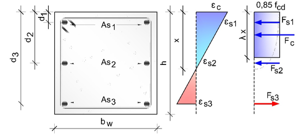
Equation 1 determines maximum compression load applied to the column; Equation 2 determines the bending strength, taking into consideration a uniaxial compression, where: fc is compressive strength; x is the neutral line; b is the section width; ε is the material strain; E is the modulus of elasticity of steel; As is the steel area; h is the section height; F is the force in the layer; d is the effective depth.
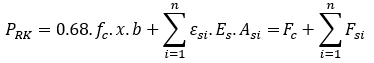
When deformation limits are established, the interaction diagram may be performed, as Figure 2 shows, where: M is the bending moment; P is the axial load. Figure 2 shows possible interactions and action plane of bending moments (Mx and My) and axial load (P), coupled to a simplification so that the bending moment may be considered only at the main direction (Mx), like studied in this current work.
 (1)
(1)
 (2)
(2)
Adorno (2004) developed a research of rectangular reinforced concrete columns submitted to uniaxial compression, in order to prove the calculation method developed by Mello (2003). The concrete presented average 40 MPa compressive strength and the experimental program was composed of 12 specimens, divided into two series: PSA and PCA. The PSA series consisted of four columns and the PCA was composed of eight columns. All of them had a rectangular cross section of (250 × 120) mm², subjected to axial load plus uniaxial bending. The bar spacing, and the minimum concrete cover followed the recommendations of NBR 6118 (2007).
By analyzing the ultimate loads, it is possible to observe that the PSA columns crushed with a higher load than the PCA series, due to the increased compressive strength. According to Adorno (2004), the initial eccentricity variation had poor influence on the critical tensile stress which was evidenced by the advanced cracking stage. The author concluded that the models tested kept the proportionality between the longitudinal deformation and the distance from the neutral axis to the rupture, confirming the validity of the Bernoulli’s principle, that the plane sections before bending remain plane after bending, which validates the model used in the present research.
Melo (2009) developed an experimental and numerical study of the behavior of hinged reinforced concrete (40 MPa) columns submitted to axial load plus uniaxial moment. In order to continue the research developed by Adorno (2004), columns with the same cross section and longitudinal reinforcement rate (1.57%) were used. The experimental program composed 24 columns divided into three series according to its length, where the main variable was the uniaxial eccentricity. The columns had a cross section of (250 x 120) mm² and bar spacing and minimum concrete cover according to NBR 6118 (ABNT, 2007) recommendations.
The experimental results showed a proper functioning of the test system, which validates the methodological procedures applied in this present research, with columns failure occurring at half height, as expected. Also, the main variable of the tests performed was the uniaxial eccentricity, what shows great influence on the columns ultimate load. A nonlinear response of the bending strength was observed as a function of the slenderness and eccentricity of the force application in the columns. Melo (2009) verified that the conservatism of the ultimate force predictions methods increases as the uniaxial eccentricity is reduced.
PROCEDURE
General characteristics
Six partially jacketed concrete columns were analyzed and submitted to axial load plus uniaxial bending. All columns were monitored by electrical resistance strain gauges (extensometers), placed longitudinally to the column to register concrete and steel’s deformation. Digital comparative monitors were employed to obtain displacements. Variables comprised the position of partial jacketing and the presence or absence of a cement-sand mortar coating. Transversal section, longitudinal reinforcement rate, compression strength, and positioning of extensometers used in the tests setup, were constant for all columns.
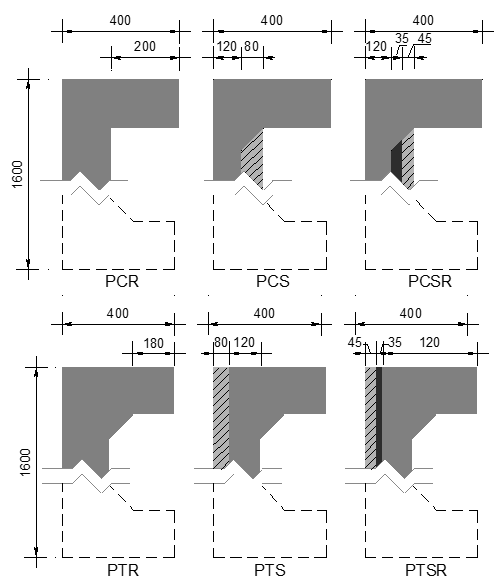
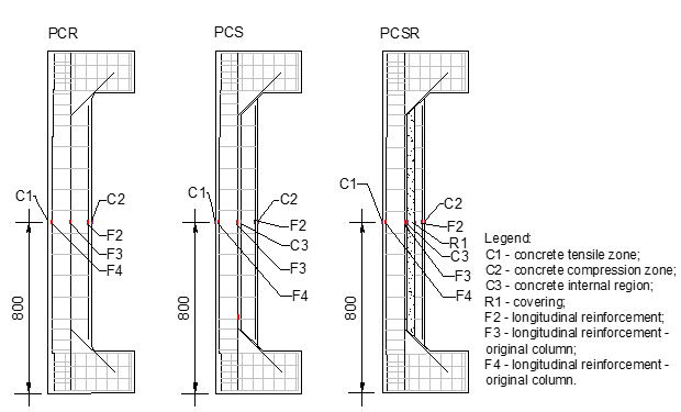
The eccentricity of axial load was 100 mm when compared to the longitudinal axis of the column´s span. The columns were divided into two groups: a group of columns strengthened in the compression zone (PCR, PCS and PCSR) and another group of columns strengthened in the tensile zone (PTR, PTS and PTSR). A control column was cast in each group, one simulating the column strengthening without the removal of the mortar coating of the original section and the other with the complete removal. Control columns featured a transversal section of (200 × 200) mm² and total length of 1.600 mm, with slenderness index of approximately 28. Strengthened columns had an initial section of (120 × 200) mm² and total length of 1.600 mm, with 80 mm of strengthening layer. After the retrofit, the columns showed a final transversal section identical to that of the reference columns. Figure 3 demonstrates the columns´ size, and the concrete corbel made to prevent premature concrete cracking in the strengthened specimens.
Reinforcement
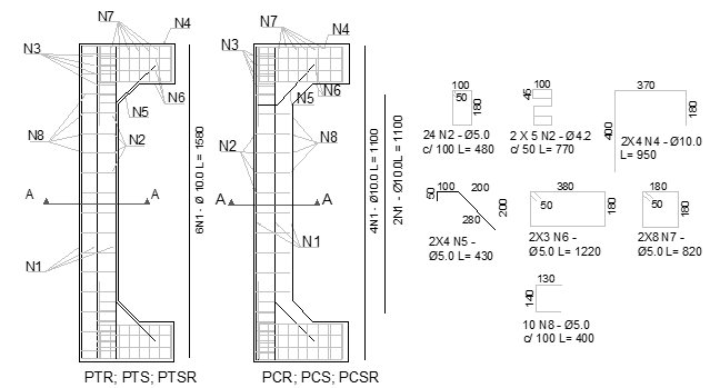
Representing conventional situation, the longitudinal reinforcement of reference columns featured 6 Ø 10.0 mm (As = 4.71 mm²), with stirrups measuring Ø 5.0 mm spaced at every 100 mm at the center, and Ø 5.0 mm for every 50 mm at the edges. Further, additional open stirrups were employed with epoxy adhesive, measuring Ø 5.0 mm for every 100 mm, later fixed in the hardened concrete to help in adherence between new and old concrete. Initial reinforcement of all columns measured 4 Ø 10.0 mm (As= 314 mm²), with two longitudinal bars added for reinforcement, meeting the number of bars used in the reference columns without any reinforcement, or rather, 6 Ø 10.0 mm (As = 4.71 mm²). Transversal reinforcement were of the same specification as that in the reference columns (Figure 4).
Instrumentation
Concrete
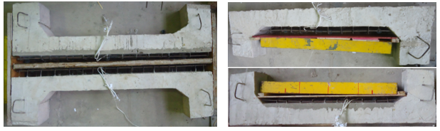
For reinforcement at the tensile and compression region of the columns, the transversal reinforcement (open stirrups) was fixed into the hardened concrete with an epoxy-based structural adhesive in 60 mm-deep holes. It comprised Ø 5.0 mm stirrups every 100 mm, simulating procedures in civil work. Posterior to the fixing of open stirrups (Figure 5), extensometers were placed on the concrete. A cement-sand mortar coating was applied to the PTSR and PCSR columns prior to the installation of the open stirrups. Another extensometer was placed on the coating surface. Longitudinal reinforcements (2 Ø 10.0 mm) were positioned to complete the positioning of the reinforcement by placing the wooden moldings and for the casting of concrete. The instrumentation of the concrete surface was finalized by placing an extensometer on the strengthening layer.
Reinforcements
Electrical resistance strain gauges were used on concrete and reinforcement bars to monitor deformations during the tests. Figure 6 shows the positioning of sensors in the columns PTR, PTS and PTSR and Figure 7 displays the placement of sensors in columns PCR, PCS and PCSR. Extensometers were positioned half way the columns´ length.
Test system
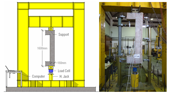
Figure 8 details the test setup used in the experimental analysis of the columns. The system comprised a highly rigid metallic frame fixed to the reaction slab, a 2000 kN hydraulic jack driven by a hydraulic pump for loading, and a 2000 kN load cell with a 0.5 kN precision, locked to a digital indicator for load recording. Columns were coupled in pinned supports, simulating hinges placed eccentrically to the columns´ axis and thus making viable the expected uniaxial compression. Extensometers were read by a computer-connected data logger, for sensors installed in the rebars and for those fixed on the concrete surface.
TEST RESULTS
Steel and concrete
The columns were pour simultaneously. Column was reinforced after 28 days of cement-sand mortar coating. Three cylindrical specimens were casted at each concreting stage and tested according to NBR 5739 (ABNT, 2007), with compressive strength (fc) 7.0 MPa and 32.0 MPa respectively for coating mortar and concrete. Concrete modulus (Ecs) was equivalent to 28.1 GPa. In the case of the steel bars, tests were performed following NBR 8522 (ABNT, 2008). Results for yielding stress (fys) and modulus (Es) were 662.0 MPa and 218.4 GPa for 5.0 mm diameter bars and 548.1 MPa and 209.2 GPa for 10.0 mm diameter bars, respectively.
Loads and failure modes
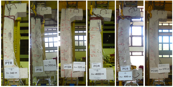
Control columns PTR (reference tensile strengthened column) and PCR (reference compressive strengthened column) revealed the concrete´s fragile failure in the compression zone near the middle span. PCR also showed failure close to edge, in the compression zone. Reinforced columns also revealed different failure modes, even though they demonstrated a monolithic behavior during tests immediately before failure. PTS reinforced column behaved monolithically immediately before failure, even though, on this occasion, the loosening of reinforcement occurred at the zone close to the upper end. A similar behavior has been registered for the mortar cover of column PTSR. PCS column, reinforced at the compression zone, revealed monolithic behavior up to column failure, without any loss or crack at the strengthening layer or the concrete interface.
The crushing of the concrete at the zone close to the edge occurred. PCRS column showed cracking pattern on the surface between reinforcement and substrate immediately prior to failure.
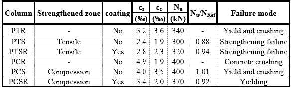
Table 1 displays failure loads, maximum tensile strain of the steel (εs) and maximum compression strain of the concrete (εc), the ultimate axial load (Nu), and the comparison between ultimate load and the load prediction (NRef) for PTR and PCR columns, and the columns´ failure modes. Failure modes were defined taking into account deformation and failure characteristics, observed experimentally. Control column PTR failed at 340 kN axial load, revealing steel deformations higher than yield (εs≥εys=2.62‰). Reference column PCR crushed at 400 kN axial load, corresponding to approximately 120% of last load provided by column PTR. Tensile strengthened columns PTS and PTSR presented failure by detachment of strengthening layer. Further, compression-reinforced columns PCS and PCSR were failed at the tensile zone with steel yielding and crushing of concrete at the compression zone, no signs of detachment were registered.
ANALYSIS OF RESULTS
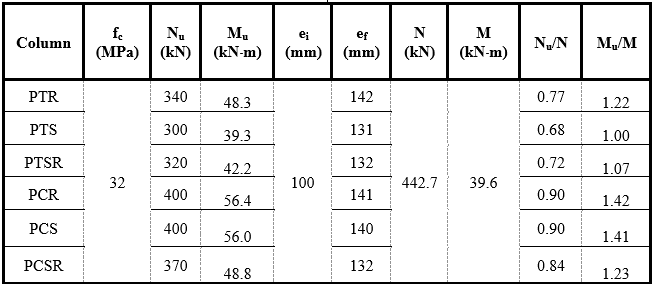
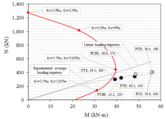
Table 2 displays experimental failure loads (Nu), experimental bending moment (Mu), initial (ei) and final (ef) eccentricities, theoretical failure load (N) and flexural strength (M) estimated by the interaction diagram, the relationship between experimental failure load and estimated load (Nu/N) and the relationship between theoretical and experimental bending moments (Mu/M). Results for the theoretical bending moment were satisfactory for the PTR, PTS and PTSR columns, at mean rate 1.09 for Mu/M; rate reached 1.36 for the PCR, PCS and PCSR columns. Cement-sand mortar covering was not significantly damaged in the two reinforcement conditions. In other words, columns reached or went beyond estimates. In the case of axial load, columns revealed experimental loads lower than the theoretical estimates. Mean result (0.88) for Nu/N was better for the columns strengthened in compression zone.
Figure 9 shows an interaction diagram (based on MacGregor & Ibrahim, 1996) of the transversal section common to all columns and their respective final experimental resistance. For any eccentricity there is a unique pair (M/N), and plotting these series of pairs corresponding to a different eccentricity the interaction diagram is obtained. The horizontal axis shows the bending moments values and the vertical axis the axial load values, so the radial lines show constant eccentricity. The more vertical radial lines the smaller eccentricity conducting to compression failure range, so the more horizontal radial lines the bigger eccentricity conducting to tension failure range. The linear load trajectory shows a proportional well balanced failure for both steel and concrete of the columns cross section according to NBR 6118 (2014). When load trajectories were compared, the second order effect, associated to physical non-linearity, decreased estimates of ultimate resistance to normal load up to 28%, whereas a mere 5% reduction occurred.
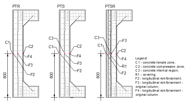
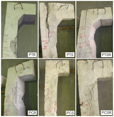
The above demonstrates that, even at low slenderness indexes, this effect should be taken into account due to decrease in the safety of the columns. Whereas Figure 10 shows post-cracking columns, Figure 11 details damaged zones. The columns strengthened in the tensile zone showed detachment of concrete layer near the column´s edge, due to the pullout of the stirrups with the failure of the column. The failure of the compressed zone at the edge of PCR column may also be noted.
CONCLUSIONS
Current test provides the experimental results of six concrete columns strengthened at different zones, tensile and compression surface, submitted to uniaxial compression. Results were analyzed taking into consideration different compression strength of the columns, strengthening zone and maximum displacements in the central zone of the columns. Maximum displacement of columns reached 44 mm, within the failure estimates and the elaboration of the interaction diagram.
The strengthened columns PTS, PCS, PTSR and PCSR showed a similar behavior, with no evident deformations on the concrete original surface, which indicates that the concrete between the strengthening layers was not crushed. The coating applied on the surface of the original section of the PTSR column did not suffer major deformations, instead of the PCSR column. The results were satisfactory since the column that presented greater loss, the PTS column, had an average loss of 35%.
The PCR, PTR, PTS and PTSR columns provided results beyond the estimates, with maximum loss of 32% for the PTS column, the one without mortar coating, with detachment immediately before failure. The control and strengthened to compression columns had the best performance among the columns under analysis. The above was corroborated by analysis made by the interaction diagram. PTSR and PCSR coated columns had a similar behavior to their respective non-coated ones (PTS and PCS), even when concrete area was reduced by approximately 20%. The partial jacketing under uniaxial compression proved to be more adequate when undertaken at the columns´ compressed zone and may be executed through conventional procedures. Regarding to removal or not of the mortar covering, tests revealed very small influence in the columns´ strength and a behavior similar to that of columns without any covering, occurring detachment immediately prior to the columns failure.
REFERENCES
Adorno, A. L. C. (2004), “Análise Teórica e Experimental de Pilares em Concreto Simples e Armado sob Flexo-Compressão Reta”, Tese de Doutorado, Universidade de Brasília, p. 300.
American Concrete Institute (2008), ACI 318: Building Code Requirements for Structural Concrete, Farmington Hills, Michigan.
Associação Brasileira de Normas Técnicas (2007), NBR 5739: Concreto – ensaio de compressão de corpo de prova cilíndrico, Rio de Janeiro.
Associação Brasileira de Normas Técnicas (2014), NBR 6118: Projeto e execução de estruturas de concreto armado, Rio de Janeiro.
Associação Brasileira de Normas Técnicas (2007), NBR 6118: Projeto e execução de estruturas de concreto armado, Rio de Janeiro.
Associação Brasileira de Normas Técnicas (2008), NBR 8522: Concreto – Determinação do módulo de elasticidade e diagrama tensão-deformação, Rio de Janeiro.
Comite Euro-International Du Beton (1983), Bulletin d’Information n. 162: Assessment of Concrete Structures and Design Procedures for Upgrading (Redesign), London.
Comite Euro-International Du Beton (1993), Model Code 1990: Design Code, London.
Gillum, A. J., Shahrooz, B. M., Cole, J. R. (2001), Bond strength between sealed bridge decks and concrete overlays, ACI Structural Journal, p.13.
Gomes, A., Appleton, J. (1998), Strengthening of Reinforced Concrete Structures by use of Jacketing, RPEE, p.67.
Guimarães, G. N., Ferreira, D. B., Gomes, R. B., Carvalho, A. L. (2016), Behavior of Reinforced Concrete columns strengthened by partial jacketing, Ibracon Structures and Materials Journal, p. 155-159. http://dx.doi.org/10.1590/S1983-41952016000100002
Macgregor, J. G., Ibrahim, H. H. H. (1996), Tests of eccentrically loaded high-strength concrete columns, ACI Structural Journal, pp. 585 - 594.
Mello, E. L. (2003), “Concreto armado: resistência limite à flexão composta normal e oblíqua”, 1ª Ed., Finatec UnB, Brasília, Brasil, p.113.
Melo, C. E. L. (2009), “Análise Teórica e Experimental de Pilares de Concreto Armado Submetidos à Flexo-compressão Normal”, Tese de Doutorado, Universidade de Brasília, p. 157.
Wight, J. K., Macgregor, J. G. (2009), “Reinforced Concrete: Mechanics and Design”. Pearson Education, New Jersey, p.516.
Author notes
denio@ufpa.br
Additional information
Cite as: D. R. C. de
Oliveira, I. I. R. Damasceno, V. H. L. Branco (2018), “Eccentrically-Compressed
Reinforced Concrete Columns Strengthened With Partial Jacketing”, Revista
ALCONPAT, 8 (2), pp. 150 - 162, DOI: http://dx.doi.org/10.21041/ra.v8i2.276
Legal Information: Revista ALCONPAT is a quarterly publication by the Asociación Latinoamericana de Control de Calidad,
Patología y Recuperación de la Construcción, Internacional, A.C., Km. 6 antigua
carretera a Progreso, Mérida, Yucatán, 97310, Tel.5219997385893,
alconpat.int@gmail.com, Website: www.alconpat.org
Responsible editor: Pedro Castro Borges, Ph.D.
Reservation of rights for exclusive use No.04-2013-011717330300-203, and ISSN
2007-6835, both granted by the Instituto Nacional de Derecho de Autor.
Responsible for the last update of this issue, Informatics Unit ALCONPAT,
Elizabeth Sabido Maldonado, Km. 6, antigua carretera a Progreso, Mérida, Yucatán, C.P. 97310.
The views of the authors do not necessarily reflect
the position of the editor.
The total or partial reproduction of the contents and
images of the publication is strictly prohibited without the previous
authorization of ALCONPAT Internacional A.C.
Any dispute, including the replies of the authors,
will be published in the first issue of 2019 provided that the information is
received before the closing of the third issue of 2018.