![]()
| Study Case | https://doi.org/10.21041/ra.v15i1.695 |
Analysis of overturning stability of a historic cemetery entrance structure
Análisis de la estabilidad ante vuelco de la estructura de entrada a un cementerio histórico
Análise da estabilidade ao tombamento da estrutura de entrada de um cemitério histórico
A. K. L. L. Nzambi1* , D. R. C. Oliveira1, M. S. Picanço1, R. S. Fernandes1., R. C. C. Norat2, T. A. B. C. Sanjad2
1 Grupo de Análisis Experimental de Estructuras y Materiales, Facultad de Ingeniería Civil, Universidad Federal de Pará, Belém, Brasil.
2 Laboratorio de Conservación, Restauración y Rehabilitación (LACORE), Facultad de Arquitectura y Urbanismo, Universidad Federal de Pará, Belém, Brasil.
*Contact author: aaronkadima@email.com
Received: 20/09/2023
Revised: 10/10/2024
Accepted: 21/11/2024
Published: 01/01/2025
| Cite as: Nzambi, A. K. L. L., Oliveira, D. R. C., Picanço, M. S., Fernandes, R. S., Norat, R. C. C., Sanjad, T. A. B. C. (2025), “Analysis of overturning stability of a historic cemetery entrance structure.”, Revista ALCONPAT, 15 (1), pp. 64 – 78, DOI: https://doi.org/10.21041/ra.v15i1.695 |
Abstract
This study assessed the safety against overturning of an old entrance structure located at the entrance of Lady of Solitude Cemetery (1850) in Belém do Pará/Brazil. A non-destructive technique using ground penetrating radar (GPR) was used to map the existing foundation and the assessment was made by analyzing the action of load on its centroid and comparing the results of the net allowable capacity of the soil with the maximum pressure exerted at the base of the foundation, also, comparing the moment resistance and the overturning moment in terms of the minimum safety factor required. The GPR results revealed the type of shallow foundation with a depth of 1 m; while the geotechnical results showed that there was no tension in contact with the base. The position of the centroid within the column kern resulted in a safety factor 10 times greater than the minimum recommended value.
Keywords: assessment; historic buildings; georadar; stone lioz; inclination.
1. INTRODUCTION
The use of shallow foundations (footings, blocks, and rafts) is a millennial practice in civil engineering, usually performed to support various structure types at a depth of up to 2.0 m. According to NBR 6122 (ABNT, 2022), shallow foundations transmit the loads to the soil directly by the tensions under the foundation base to a depth of, at most, twice the smaller dimension of the foundation element. Its execution is practical and less costly than the deep foundation. However, their application is less confident than that of deep foundations when it comes to providing long-term safety; due to the risk of soil failure as its properties change over time. The problem of shallow foundation instability is recurrent in old buildings due to several factors, mainly the soil profile, the wear of the material used in the foundation over time, the changing water level, and the ground's excessive vibration. In Brazil, the city of Santos (Brazil) is known as the city of inclined buildings, where about 10% of the city's buildings constructed on the Santos waterfront in the 1960s have a slope problem due to vertical displacements caused by densification of the fine soil over the marine-type soil along the time. The best-known case is the Núcio Malzoni building (Figure 1a) which in 2013 presented a tilt of 2.17º and plumb displacements (δ) of 2.10 m. The Tower of Pisa (Figure 1b) and the Bad Frankenhausen tower (Figure 1c) are the most famous cases worldwide, which showed displacements of 4.03 and 4.60 m, respectively. In the tower of Pisa (Italy), the inclination was caused by the fluctuating water level that strongly influences the movement of the ground. While in the Bad Frankenhausen tower (Germany), the tilt was caused by the salt-bearing rock layers in contact with groundwater.
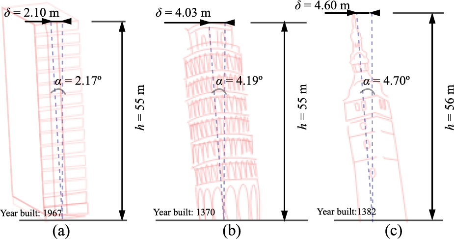
Figure 1. Núcio Malzoni Tower; (b) Pisa and (c) The leaning tower of Bad Frankenhausen Note: (α = arctan(δ/h)).
However, the construction processes and the materials used in the old buildings, such as sand-lime or clay mortars, are permanent challenges of compatibility and the methodology to be adopted in the case of restoration or structural reinforcement (Radnic et al., 2020; Briceño-Mena and Castro-Borges, 2022) with the emergence of Portland cement and reinforced concrete, respectively, at the end of the 19th and the 20th centuries. Another major challenge in the case of the risk of overturning is the technique to be employed in the evaluation of old foundations, joining the recurrent difficulties of the lack of technical documentation and norms referring to the safety of structural stability of old buildings.
In general, the solutions to remedy the inclination problem in old buildings must be treated case by case and depend mainly on the structure's self-weight, the structural monolithicity, and the type of foundation, including the soil profile. Several techniques are employed for stabilizing the vertical plumb or the ground settlement, such as the use of jacking systems (Maffei et al., 2006), the leveling technique with soil extraction, under-excavation or sub-excavation (Tamez et al., 1997; Edmunds, 1993), the use of the load transfer and water table control mechanism. In addition, other solutions can be applied, such as improving the soil's load-bearing capacity; expanding the load transmission area; replacing the old foundation with a new one; stabilizing by retaining structures; and inserting structural elements such as piles, micro-piles, and efficient drainage (Burland et al., 2009; 2015).
The Amazonian city in the state of Pará has countless architectural, urban, and landscape assets inherited from Portuguese, French, Italian, and Japanese influence since for a long time the city was the main transit point for rubber exports to Europe. Thus, it is possible to find several old buildings protected by Brazil's National Historic and Artistic Heritage Institute (IPHAN), such as the Nossa Senhora da Soledade cemetery (Lady of Solitude Cemetery), located in the noble neighborhood of Batista Campos, according to Figure 2. Figure 3 shows also an illustration of the types of entrance gate frames found in the Soledad Cemetery: (a) built with stone blocks and (b) built with reinforced concrete. In this work, the safety of one of the old entrance structures (Figure 4) to the Soledade Cemetery, which had an apparent slope, was technically assessed. Due to the structure's historical value, the characterization and dimensions of the foundation were located using a non-destructive method, with Ground-Penetrating Radar (GPR) equipment. The assessment was made by analyzing the load distributed in one of the columns about to its centroid and comparing the results of the net allowable bearing capacity of the soil with the maximum pressure exerted at the base of the foundation, also, comparing the moment resistance and the overturning moment in terms of the minimum safety factor required.
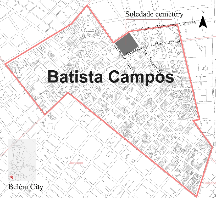
Figure 2. Location of the Lady of Solitude Cemetery.
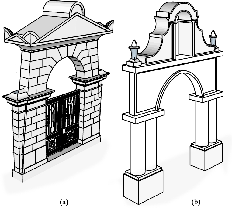
Figure 3. Illustration of types of entrance gate frames found in the Soledad Cemetery: (a) built with stone blocks and (b) built with reinforced concrete.
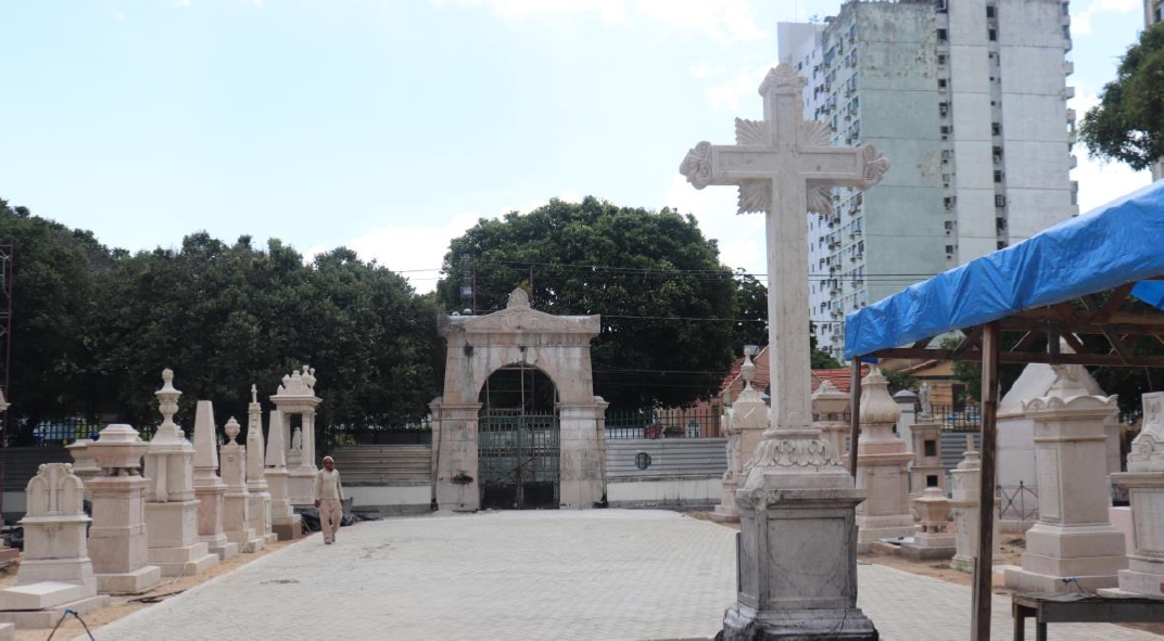
Figure 4. View of the location of the analyzed structure from inside the cemetery.
2. METHODOLOGY OF EVALUATION
2.1 Stone entrance gate frame characteristics
According to IPHAN, the Soledade structure entrance was designed by architect and engineer Pedro José Pezerat, built with stone Lioz, also known as royal stone (a historical Portuguese natural stone or type of limestone originating from the Lisbon region that has been used for centuries in public buildings), in 1850 with a triangular pediment and acroteria in stylized leaves and has a wrought iron gate produced by the English firm Singlehurrts & Muller Co., as illustrated in Figure 5. The non-monolithic structure is composed of an assemblage of carved stone blocks. The height, length, and width were ~8.0 x 6.0 x 0.65 meters, respectively, and the self-weight was estimated at 45 tf.
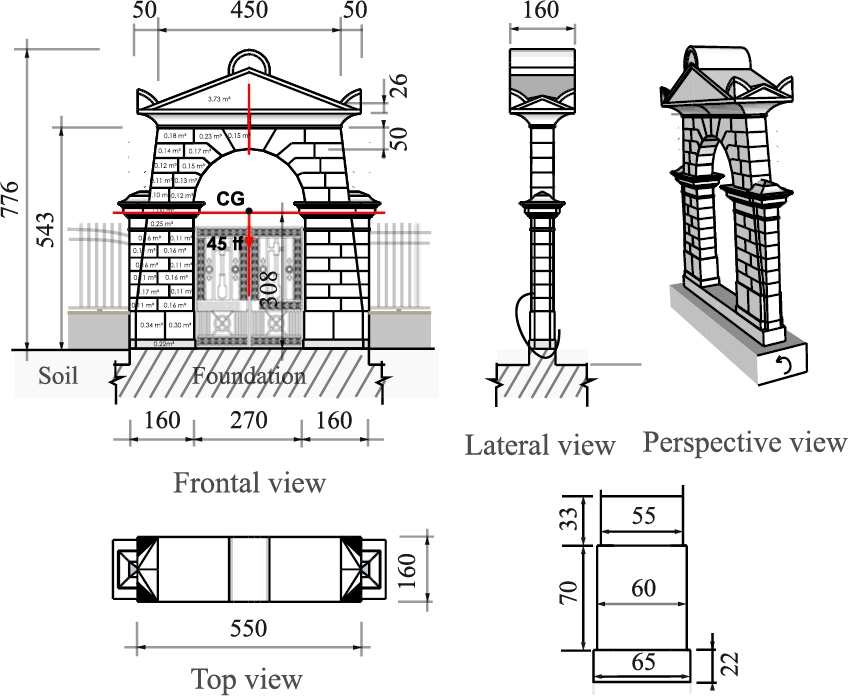
Figure 5. Gate frame dimensions (unit: cm)
2.2 GPR surveys for the detection of existing foundations
According to the report of the drilling of the STP (Surface-Treating Pressure), the soil profile is of yellow sandy silt type with average compactness up to 9 m depth, presented in Table 1. The mapping of the foundation was performed with the GPR, also known as Georadar. GPR is an electromagnetic geophysical method that uses pulses of radio waves at certain frequencies to map and identify underground structures. This practical methodology detects the depth, composition, and presence of objects or anomalies in the subsoil, avoiding the necessity of excavations. It is considered a non-intrusive and low-cost method of surveying the subsurface and is used in various applications for the preservation of buildings with historical value, as well as in archaeological investigations (Hussain and Akhtar, 2017). Table 2 presents the characteristics of the GPR equipment used, as shown in Figure 6a, which has a 500 MHz antenna frequency and works in the time domain in data post-processing. The detections were made in the proximities parallel to the structure at 30, 60, 90, and 120 cm positions, according to Figure 6b. According to the processed radagrams presented in Figure 7, it was possible to observe different GPR signal responses in the soil along the structure, such as longitudinal discontinuities in the fill materials, indicating the existence of inhomogeneities in a single material, the irregular shapes and sizes of the reflection images generated revelated the existence of stones, and the different behavior of the strongest signal may be an indication of the presence of cementitious material, in other words, cyclopic concrete was used in the shallow foundation, as shown by the signal intensity at a depth of up to ~1.0 m and along the parallel positions to the structure.
Table 1. Soil layer profile results
| Layer | Depth (m) |
Thickness (m) |
Nspt* | Soil type | Compactness |
| 1 | 1.0 to 7.0 | 6.0 | 13 | Sandy yellow silt | M. Compacted |
| 2 | 7.0 to 9.0 | 2.0 | 45 | Medium red silty sand | Highly compacted |
| 3 | 9.0 to 13.5 | 4.5 | 50 | Yellow silty fine sand |
Note: Nspt* = average value of soil penetration resistance index; The water was found at a depth of 9.21 m to 9.43 m; M. = medium.
Table 2. GPR and soil physical characteristics
| Target | Antenna center frequency (MHz) | Soil type | Scan method | Data analysis method |
| Soil | 500 | Sandy silt | linear | Time domain |
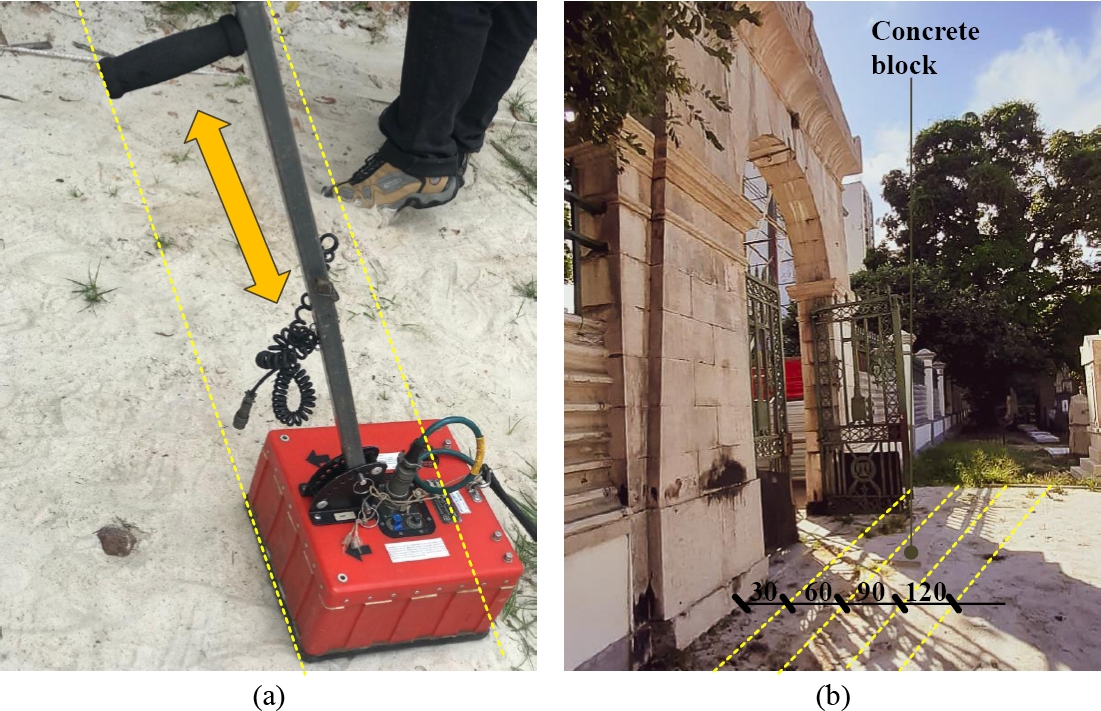
Figure 6. (a) GPR used and (b) Positions investigated.
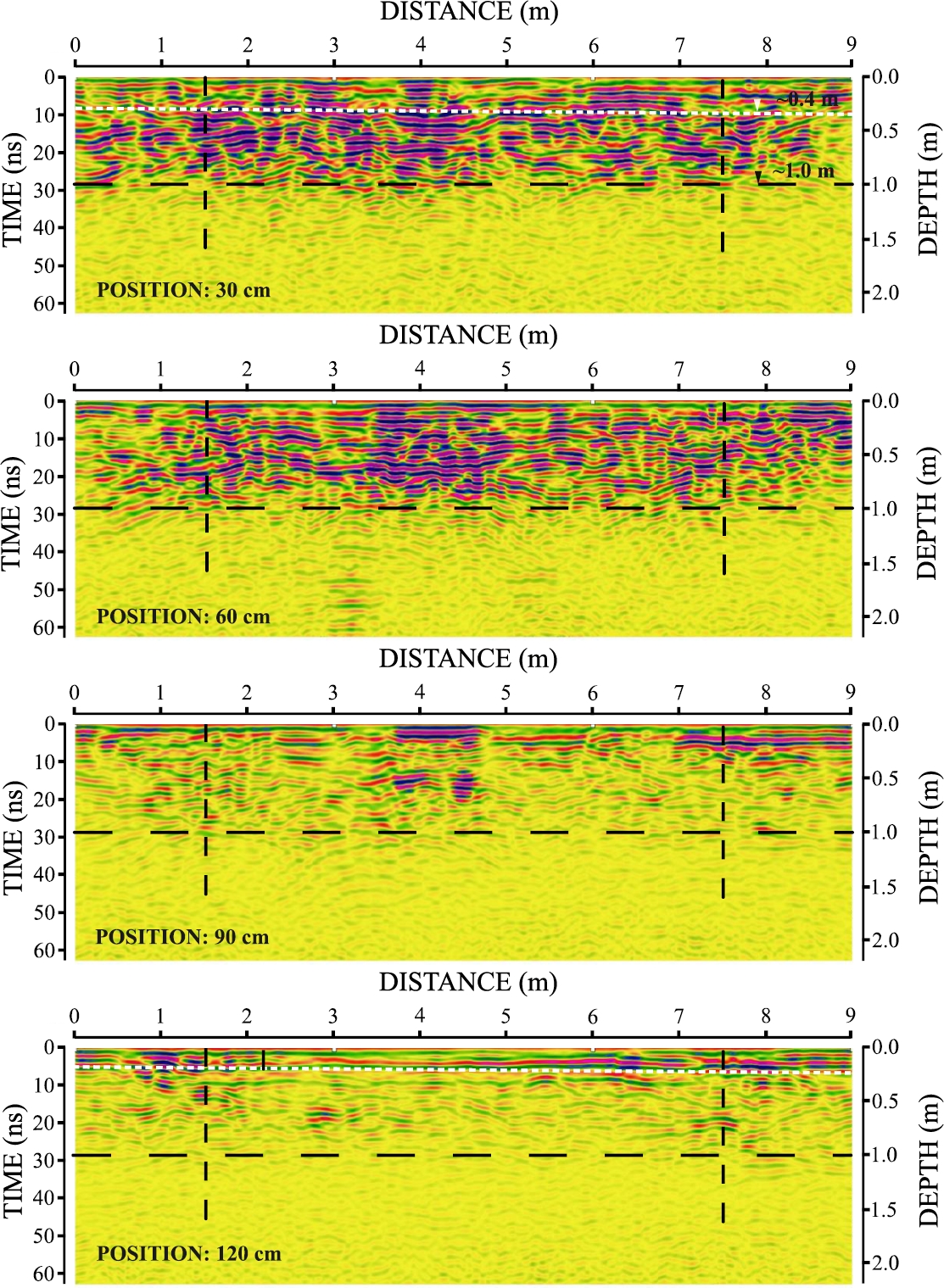
Figure 7. Foundation Radagram.
It was noted that the signals were intense up to the 60 cm position, while at the 90 cm position, the presence of the signal was identified only in the middle, this was due to the existence of a concrete block extending up to this position, as can be seen in Figure 6b, whereas the radagram at the 120 cm position did not identify any stone in this position. For validation of the mapping results, 20 cm drills were made on both sides parallel to the structure, as shown in figures 8a and 8b, thus, the extension of the foundation block was proven at 80 cm position and the backfill layer at 40 cm.
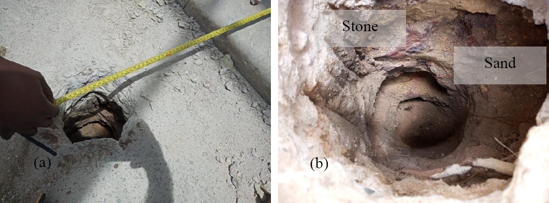
Figure 8. Checking the extension of the foundation block: (a) from outside the cemetery and (b) from inside the cemetery.
2.3. Inclination and eccentricity
According to Spyrakos and Nikolettos (2005), overturning occurs by rotation around the center of gravity (CG). However, a tilt of 1.35º was observed, probably due to settlement over time, traffic, or the movement of soil during excavation for the asphalting of Serzedelo Street, generating an eccentricity of 7.26 cm in the direction of the y-axis. In the direction of the x-axis, the structure did not exhibit any inclination. The Plumb line method was adopted for measuring the eccentricity, as illustrated in Figure 9. The results were computed using equations 1 and 2.
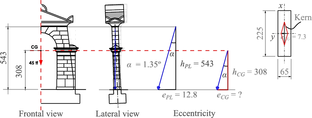
Figure 9. Assuming eccentricity by plumb line method. (unit: cm)
| (1) |
| (2) |
Where:
and are eccentricity at the height of the plumb line and the center of gravity, respectively.
and are heights of the plumb line and center of gravity, respectively.
2.4. Ultimate and allowable soil-bearing capacity
The ultimate bearing capacity (qu) for the continuous footings in the sand layer (no cohesion) was calculated according to Terzaghi's (1943) and Meyerhof's (1963) expression, Equation 3, and the allowable bearing capacity (qa) was calculated by Equation 4. The influence of the angle of internal friction was also evaluated, varying from 30° for the loosely compacted soil profile, 35 and 40° for the medium compacted soil, defined according to the classification of sandy soils proposed by Porto (1979) and by the geotechnical properties shown in Table 3.
| (3) |
| (4) |
Where:
γ = soil unit weight.
sγ and sq = shape factors.
B = footing width.
q = total surcharge, q = γ‧D.
D = depth of embedment.
Nγ and Nq = bearing capacity factor for soil unit weight and for the surcharge, respectively.
FS = safety factor.
Table 3. Geotechnical properties
| Sandy soil layer | f (degrees) |
N | γ (t/m³) |
Continuous footing shape factors | Bearing capacity factors (AASHTO, 1996) | ||
| sq | sγ | Nq | Nγ | ||||
| LC | 30 | 4 | 1.8 | 1.0 | 1.0 | 18.40 | 22.40 |
| MC | 35 | - | 1.9 | 33.30 | 48.03 | ||
| 40 | 64.20 | 109.41 | |||||
Note: N is the average SPT at the stress bulb (twice the width of the foundation); f is the soil friction angle, f = 28º + 0.4‧N (Godoy, 1983); the angles of 35 and 40° were defined by the Porto classification (1979); LC = loosely compacted soil; MC = medium-compact soil.
2.4.1. The effects of eccentric loading and base inclination
For the effect of load eccentric relative to the centroid of the footing, reduced footing width was calculated according to Equation 5. Also, it was assumed the inclination of the base, through the factors bγ and bq, calculated according to Equation 6. Therefore, the modified ultimate bearing capacity is given by Equation 7 and the net allowable bearing capacity was calculated according to Equation 8.
| (5) |
| (6) |
| (7) |
| (8) |
Where:
B' = Effective footing width.
3. RESULTS AND DISCUSSION
3.1 Safety criteria
Combined axial force and moment increase the pressure on an edge or corner of a base. If the pressure combination is in tension, this effectively means that the contact between the soil and the base has been eliminated and the pressure is zero (qmin = 0). To avoid zero pressure, the eccentricity must be inside the kern and the maximum bearing pressure (qmax) must not exceed the net allowable soil pressure (q’net,a), according to the criteria in Equation 9. Equation 10 establishes the safety requirement against overturning of the structure, where the ratio of all the resisting moments (MR) over the overturning moments (Mo) is defined as the factor of safety (FS). Overturning is considered in design and in check of existing structure of such that the MR must be greater than the Mo, by a FS of at least 1.5.
| (9) |
| (10) |
3.2 Calculation of the acting forces on the foundation
Table 4 presents the parameters used to calculate the forces acting on the column (self-weight, Pc), the overburden (soil cover or backfill, W1), and the foundation (W2 and W3), defined respectively by Equations 11, 12, 13, and 14, as shown in Figure 10. The total vertical load (PV) was calculated according to Equation 14 and the moment due to the centroid (Mtilt) of the column was calculated according to Equation 15.
Table 4. Characteristic parameters used
| Soil cover | Black stone block | ||||||
| h1 (m) | b (m) | L (m) | γ1 (tf/m³) | h2 (m) | B (m) | L (m) | γ2 (tf/m³) |
| 0.4 | 0.8 | 1.6 | 1.8 | 0.6 | 2.25 | 1.60 | 2.67 |
Note: γ1 and γ2 = soil and cycloptic concrete unit weight, respectively.
| (11) |
| (12) |
| (13a) |
| (13b) |
Where:
Pc = load on the footing from the column.
W1 = weight of soil.
W2 = weight of footing pedestal.
W3 = weight of footing base.
L = depth of the foundation block considered in this work.
b = soil cover width.
B = footing width.
Bp = pedestal width.
h1 = Soil cover depth.
h2 = footing thickness.
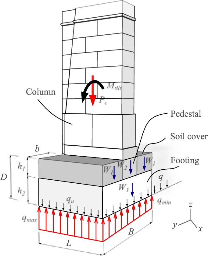
Figure 10. Assumed forces acting on stabilizing of column foundation.
| (14) |
| (15) |
Where: PV = total vertical load and Mtilt is the moment due to eccentricity.
3.3 Calculation of the minimum and maximum pressures in contact with the footing base
Knowing the forces and moment acting on the structure, the minimum (qmin) and maximum (qmax) pressures in contact with the foundation block (pressure distribution under the footing) were calculated according to Equation 16. The qmin result revealed the contact between the soil and the base, so there is no tension, and the difference between qmax and qmin was around 30%.
| (16) |
Where:
Therefore,
3.4 Verification against overturning
Equations 17 and 18 were used to compute the resisting (MR) and overturning (Mo) moments, respectively. Analyzing the results presented in Table 5, it was noted that all the safety factors were largely satisfactory. Varying from 2.4 to 12 for the soil resistance. In addition, a behavior of SF duplication was observed with each 5° increase in the friction angle, in other words, in an unsaturated soil, with consolidation over time, its resistant capacity can increase even more, justifying the stability condition observed in the structure analyzed, where the FS for overturning was 22, 10 times higher than the minimum value recommended by ACI 318 (ACI, 2019). This discrepancy was because the eccentricity was much smaller, resulting in a smaller overturning moment, in other words, it proved that loading with the centroid inside the column's kern does not generate a risk of overturning.
| (17) |
| (18) |
Table 5. Summary of structural safety verification
| φ (°) |
Soil | Overturning | Eccentricity | |||||||
| qmax (tf/m²) |
qu (tf/m²) |
qa (tf/m²) |
q'net,a (tf/m²) |
FS1 | FS2 | MR (tf‧m) |
Mo (tf‧m) |
FS | eCG ≤ B/6 | |
| 30 | 9.88 | 78 | 26 | 24 | 2.6 | 2.4 | 35.12 | 1.63 | 22 | 0.073<<0.375 |
| 35 | 166 | 55 | 52 | 5.5 | 5.3 | |||||
| 40 | 356 | 119 | 111 | 12.0 | 11.2 | |||||
Note: FS1 = qa/qmax; FS2 = q'net,a/qmax and FS = MR/Mo.
4. CONCLUSIONS
Based on the results, it was found that the structure is in a state of safety against overturning, with soil safety factors ranging from 2.4 to 12 and the overturning safety factor 10 times greater than the minimum required. However, the centroid analysis methodology and the use of GPR to map the existing foundation were decisive and satisfactory. This practical assessment methodology used in this work aims to be an alternative in the preliminary technical assessment of historic buildings with low cost and considerable time savings in the engineer's decision-making.
5. ACKNOWLEDGMENTS
The authors thank the Institute of Ecological Research in the Amazon (IPEAM), the Laboratory of Conservation, Restoration and Rehabilitation (LACORE) of the Federal University of Pará (UFPA) and the research group of the Geophysics for their support in the development of this study.
6. REFERENCES
American Association of State Highway and Transportation Officials. (1996). AASHTO: Types of loads and composite beams and girders. Washington, DC.
Associação Brasileira de Normas Técnicas. (2014) NBR 6118: Design and execution of reinforced concreteworks. Rio de Janeiro, Brazil (in Portuguese).
Associação Brasileira de Normas Técnicas. (2022) NBR 6122: Projeto e execução de fundações. Rio de Janeiro, Brazil.
American Concrete Institute. (2019). ACI Committee 318: Building Code Requirements for Reinforced Concrete. Detroit, MI, USA.
Briceño-Mena, J. A., Castro-Borges, P. (2022), Practical use of the safety factor in the column repair strategy of a concrete building with historical value, Revista ALCONPAT, 12 (1), pp. 98 – 109, https://doi.org/10.21041/ra.v12i1.569.
Burland, J. B. et al. (2009), Leaning tower of pisa: behaviour after stabilization operations. International Journal of Geoengineering Case Histories, 1(3): 156-169, https://www.geocasehistoriesjournal.org/pub/article/view/ijgch_1_3_2.
Burland, J. B. et al. (2015), Underexcavating the tower of pisa: back to future. eotechnical Engineering Journal of the SEAGS & AGSSEA, 46(4): 126-135.
Edmunds, H. (1993), The use of underexcavation as a means of stabilising the Leaning Tower of Pisa: scale model tests. MSc thesis. Imperial College, London.
Godoy, N. S. (1983), Estimative of pile bearing capacity from static penetrometer results. Engineering School of São Carlos - USP. (in Portuguese)
Hussain, A., Akhtar, S. (2017), Review of Non-Destructive Tests for Evaluation of Historic Masonry and Concrete Structures. Arabian Journal for Science and Engineering, 42, 925–940, https://doi.org/10.1007/s13369-017-2437-y.
IPHAN, available from: https://www.ipatrimonio.org/belem-cemiterio-de-nossa-senhora-da-soledade.
Maffei, C. E. M., Gonçalves, H. H. S., Pimenta, P. M. (2006), The pumbling of 2.2° tilted Núncio Malzoni Building. Geotecnia. 106(06):133-161, https://doi.org/10.14195/2184-8394_106_7.
Meyerhof, G. G. (1963), Some recent research on the bearing capacity of foundations. Canadian Geotechnical Journal, 1(1), 16-26, https://doi.org/10.1139/t63-003.
Radnic, J., Matesan, D., Ante Abaza, A. (2020), Restoration and Strengthening of Historical Buildings: The Example of Minceta Fortress in Dubrovnik. Advances in Civil Engineering, https://doi.org/10.1155/2020/8854397.
Spyrakos, C. C., Nikolettos, G. S. (2005), Overturning Stability Criteria for Flexible Structures to Earthquakes. Journal of Engineering Mechanics 131(4): 349-358, https://doi.org/10.1061/(ASCE)0733-9399(2005)131:4(349).
Tamez, E., Ovando, E., Santoyo, E. (1997), Underexcavation of Mexico City’s Metropolitan Cathedral and Sagrario Church. Proc. 14th Int Conf. Soil Mech & Foundtn Engrg. Hamburg: 4:2105-2126.
Terzaghi, K. (1943), Theoretical Soil Mechanics. WileyPublishing, New York, USA, http://dx.doi.org/10.1002/9780470172766.