![]()
| Basic Research | https://doi.org/10.21041/ra.v14i1.714 |
Diagnosis and structural underpinning project of the Tampieri Palace
Diagnóstico y proyecto de recalce estructural del Palacio Tampieri
Diagnóstico e projeto de reforço estrutural do Palácio Tampieri
1 Facultad de Arquitectura, Universidad Nacional de Córdoba, Córdoba, Argentina.
2 Departamento de Construcciones Civiles, Facultad de Ciencias Exactas, Físicas y Naturales, Universidad Nacional de Córdoba, Córdoba, Argentina.
*Contact author: arqzanni@gmail.com
Received: 07/11/2023
Revised: 18/12/2023
Accepted: 27/12/2023
Published: 01/01/2024
| Cite as: Zanni, E., Capdevila, J. (2024), “Diagnosis and structural underpinning project of the Tampieri Palace”, Revista ALCONPAT, 14 (1), pp. 96 - 114, DOI: https://doi.org/10.21041/ra.v14i1.714 |
Abstract
The diagnosis and structural underpinning of the Tampieri Palace is detailed, within a comprehensive restoration project. The building has a high patrimonial value, constituting one of the two existing palaces in the Province of Córdoba, Argentina. It presents fractures in load-bearing masonry, caused by differential settlements, as it is founded on collapsible silts affected by cyclical variations in the water table. The methodology consisted of relieving the existing injuries, conducting searches and technical and historical investigation of its construction to diagnose its structural and constructive state. The intervention was divided into two stages: A) stabilize and seal the building, and B) rehabilitate and restore facades and interiors. It is concluded that the driven micropiles constitute a valid alternative to refund buildings in saturated soils, with minimally destructive interventions.
Keywords: heritage; restoration; settlements; underpin; micropiles.
1. INTRODUCTION
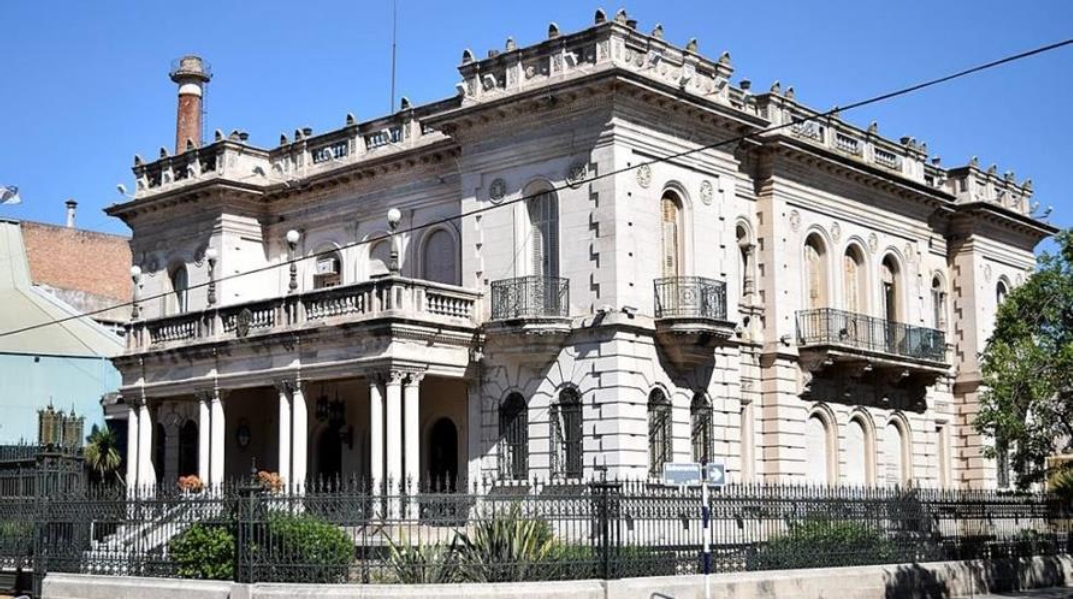
The Tampieri Palace, located in the city of San Francisco (east of the province of Córdoba, Argentina), was built in a historical context in which the migratory flow from Italy to Argentina was shocking. Its original owner, Ricardo Tampieri, one of the most important businessmen in the country, ordered his residence to be built next to the pasta factory with which he made his fortune (Figure 1). The building has a covered and semi-covered area of 1517m2 distributed over 3 levels, according to the following detail:
Basement Area (BA): 545,98m2
Ground Floor Area (GA): 545.98m2 + 31.48m2 semi-covered 1st Floor Area (FA): 373.13 m2
Machine room area (roof terrace): 20.70 m2
Figure 1. Exterior view of the palace
2. CONSTRUCTION TECHNOLOGY
The construction technology used refers to load-bearing walls made of solid ceramic bricks of 0.60m and 0.40m thickness on exterior and interior walls, respectively. There are also 15cm non-load-bearing partition walls. The foundations are continous, formed by lower widening of masonry walls, in order to transfer contact stresses compatible with the bearing capacity to the supporting soil. The width of these is 80 and 60cm, respectively, at a lunge horizon of -4.50m (-1.50m below the floor level of the BA).
The soil study reports highlights the presence, up to a depth of -10.00m, of silts and clayey silts with low resistance to surface penetration and increased compactness for depths greater than -8.00m, inferring potential collapse behavior due to wetting under applied load, especially at depths of up to 5m or 6m. It is also important to mention that the same geotechnical studies show the detection of a carbonate structure with characteristics of "tosca" distributed in a random and non-uniform way. This situation generates differential settlements in the structure due to the different behaviors of the supporting soil on account of the rise in the table water, indicated in the geotechnical reports as variable between -1.10 and -2.30m. This level exceeded, at the time of the intervention, the foundation depth of the support structure, situation that has been maintained for two decades (Videla et al., 2015).
The horizontal enclosures are made by means of IPN metal profile slabs with brick vaults and a reinforced concrete compression layer on mezzanines and roof.
The original ceilings are reinforced and consist of sheets of expanded metal (in some places with wooden slats) finished with thick and fine gypsum plaster.
The carpentry has wooden frames and leaves and includes roller blinds on the windows and door/windows.
The flooring varies depending on the room considered, showing different options such as parquet floors with marquetry on wooden battens, reconstituted granite mosaics and calcareous tiles. There are marble floors in some specific areas of the building.
The exterior finish is stone-like plaster with shanks and padding at the corners. They have ornaments, mouldings and decorative scrolls under cornices.
The interior cladding is also variable, from plaster with mouldings and moulded panels, to wooden and marble boisseries in the main rooms.
3. SOIL CHARACTERIZATION
The stratigraphic profile of the soil shows the following layers:
4. DECLARATIONS OF PROTECTION
The building is part of the Cultural Heritage of the Province according to Decree 49/94 (January/1994) which declares it a Monument of Provincial Interest. It also has a Declaration of Municipal Interest as a Historic, Cultural-Architectural Monument, according to Municipal Ordinance 6416/13 (December/2013) of the city of San Francisco.
The level of protection classifies it as Category 1: Building of Singular Quality (Integral Protection).
5. WORK METHODOLOGY
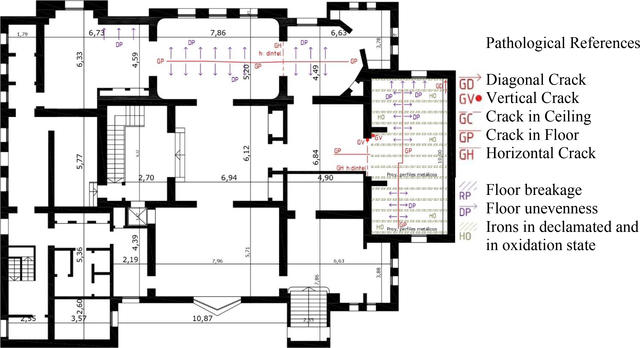
A detailed architectural and pathology survey was carried out on floors and façade, supported by a photographic record of each location. Prospections of foundations and other items were also carried out to determine the construction technology, as well as measurements of moisture content in walls and roofs, using surface contact hygrometers (multi- calibrated 8mm electrodes -for wood and porous solids-, and deep probe with 200mm electrodes).
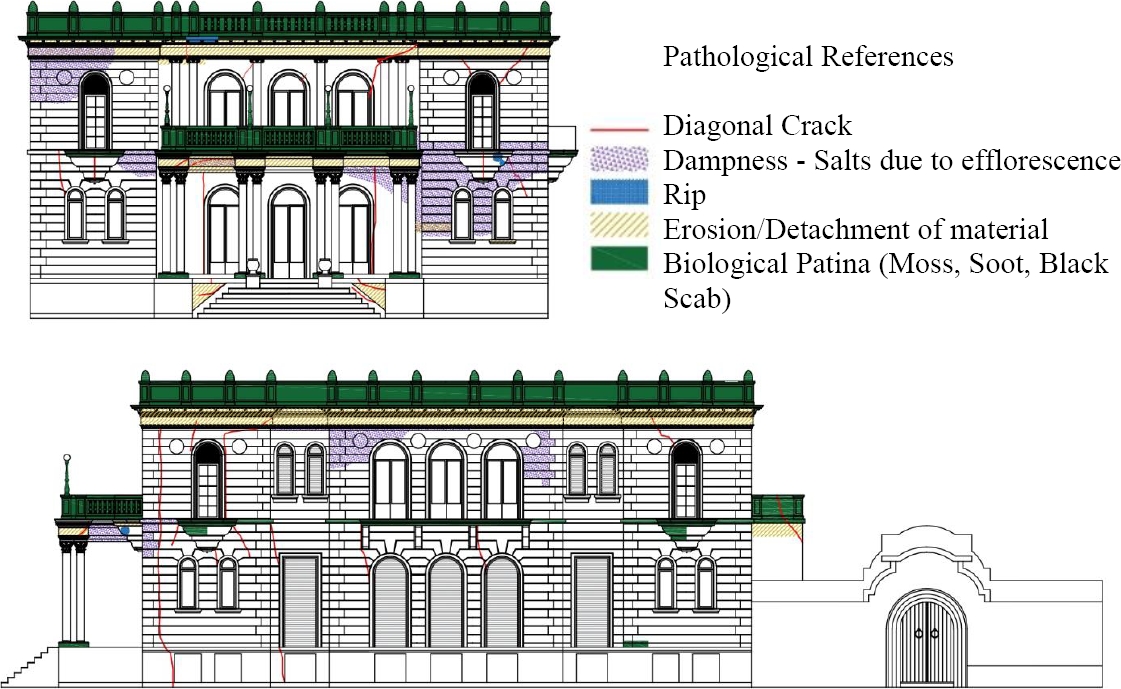
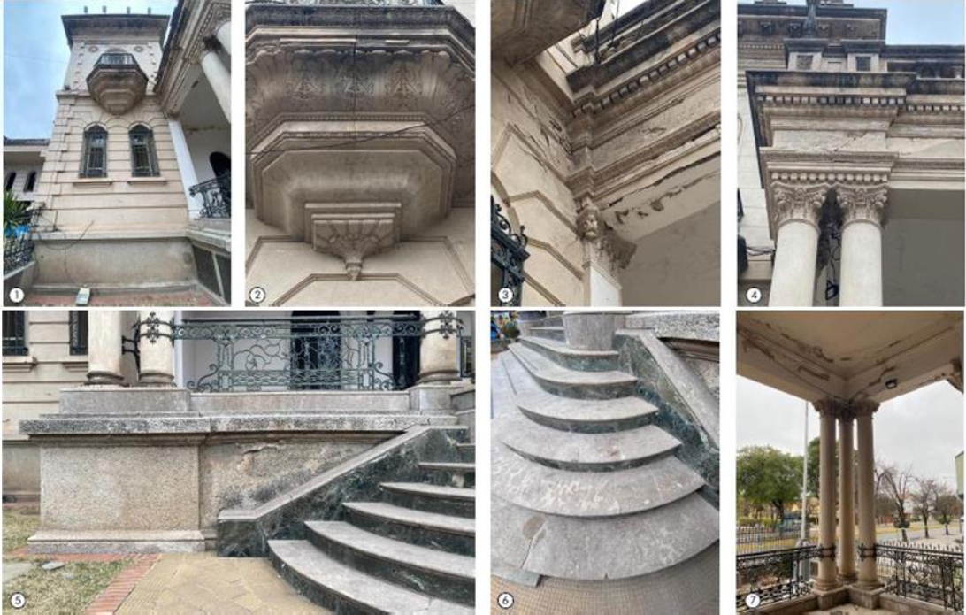
Figures 2 to 4 present diagrams, in plan and façade, of the pathological surveys carried out. The study and analysis allows us to infer the causes that probably originated them. Figure 5 shows a photographic survey of the palace's degrades.
Figure 2. Pathology survey at subsoil level.
Figure 3. Pathology survey at ground floor level.
Figure 4. Survey of pathologies on North and West façades.
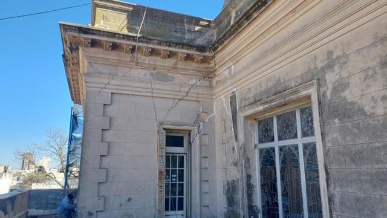
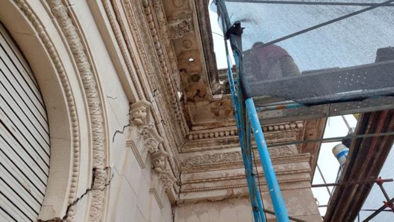
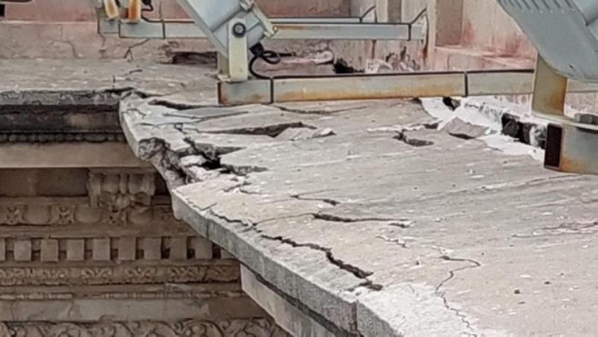
Figure 5. Photographic survey of gradients. 5.1) and 5.2): cracks in the lower coating of the balcony, caused by corrosion of the interior reinforcement structure. 5.3), 5.4) and 5.7): The displacement of the lintelled metal structure of the entrance porch, due to differential seats, caused pulling and tensile cracks in the joints with load-bearing walls, giving rise to the entry of water seepage and the consequent degradation of stone-like plaster. 5.5) and 5.6): differential descents of terrace columns over entrance porch, with warping of molding lines and breakage of cladding plates, even in stairways.
Based on the survey and analysis of the existing fractures, their causes were diagnosed, reaching the conclusion that they are due to differential settlements of the structure, due to deformation of the supporting soil, originated by its saturation. The loessic silts of the central part of Argentina have particular granulometric characteristics, being formed by a fraction of the size of sands and a significant fraction of the size of silts, clays and calcium carbonates. In general, these soils have low plasticity and stratum strengths or thicknesses that vary regionally. In the sector under study, it is very common for silt strata to appear at depths varying between 8 and 12 meters with presence of isolated nodules, with lower hydraulic conductivity than the upper silts, so that the water that infiltrates tends to accumulate above this layer. Regionally, there is a slight slope in the terrain, characteristic of wind deposits, which gives rise to the presence of depressions and wetlands. The latter is in addition to the increasing values of water surpluses in the balances, increasing from the 1970’s onwards the frequency of years with excesses. Hydrological balances show that the storage of these surpluses in these lowland systems results in a significant increase in water tables (Gómez et al., 2006).
Silty soils of loessic origin have a macroporous structure and undergo large variations in volume, called collapse, when the moisture content or stress state increases. In general, it can be stated that the tensile-deformational behavior of the Argentine loess is highly dependent on the moisture content of the soil, with a significant drop in the elastic modulus being observed when complete saturation occurs. This behavior can be attributed to the fact that increasing the moisture content of the soil, the hydration of the clay bridges and the salts precipitated at the contacts between larger particles produce the collapse of the structure and softening of the soil skeleton. As a consequence, this weakening of particle contacts is evident, at the macro scale, with an increase in vertical ground deformations (even under constant load) (Francisca, 2007). Consequently, civil constructions and architectural buildings, supported or founded on these soils, suffer significant damages. The magnitude of the damage increases with the level of the loads transmitted to the ground and with the structural typology of the construction. Figures 6 to 9 show some of the structural damage detected and surveyed at Tampieri Palace.
Figure 6. The differential seats caused diagonal tensile forces on the walls, resulting in the appearance of parabolic cracks perpendicular to the tensile diagonal.
Figure 7. Detail of cracks with displacement between wall fragments.
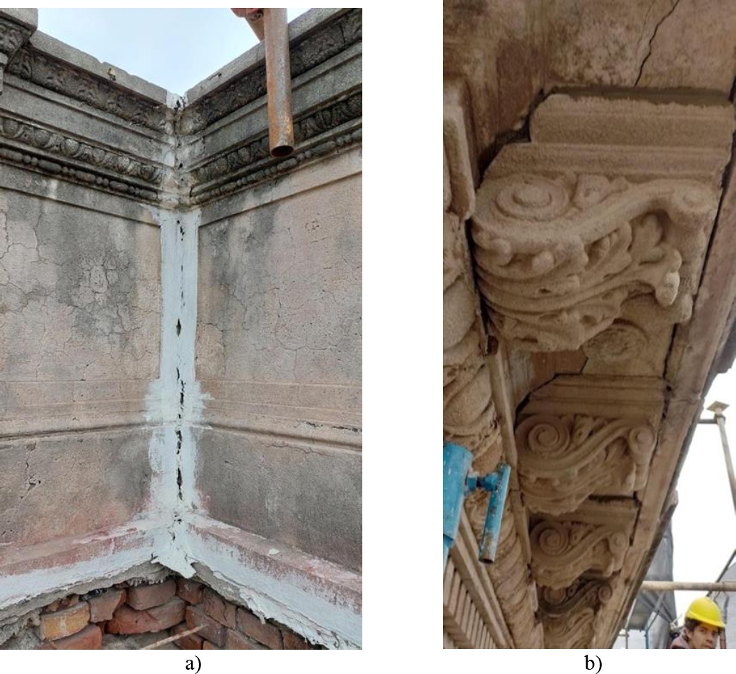
Figure 8. a) Disconnection of walls at corner encounters, due to differential displacements and collapses between them. b) Detail of detachment of ornaments and volutes due to deformation of the cornices, as a result of the settlements. Such loose elements pose a risk of falling into the void.
Figure 9. Deformation and breakage of the metal structure of the cornice frame.
Based on the above, the corresponding underpinnings were designed and calculated, opting for the technology of single-core metal micropiles driven with IGU injection (Global Unit Injection).
6. DETAILS OF THE INTERVENTION
6.1 General
In order to ensure the stability of the building against settlements, 101 driven micropiles were designed, calculated and executed, intended to transfer the loads to a stable non- collapsible stratumte (rough located at -12 m of natural ground level (Cisneros et al., 2014).
The minimum required bearing capacity of each micropile is 20 tons for each unit, in order to be able to transfer the load of the most loaded wall with a safety coefficient of no less than 50%.
The execution of mechanically drilled and concreted in situ piles was discarded as an option, due to the impossibility of carrying out the excavation inside the rooms and the risk that manual excavation would imply, given the conditions of saturation of the soil, and the possible presence of crumbling sinkholes.
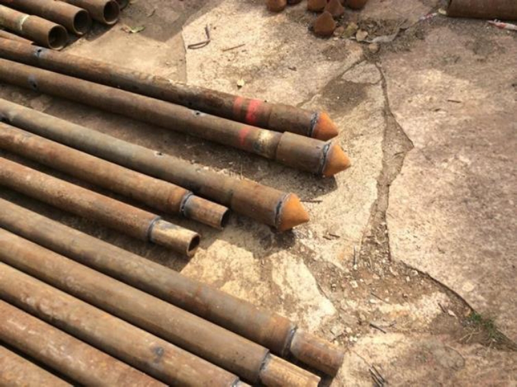
These micropiles consist of seamless, special alloy steel pipes with tensile stress that duplicate traditional structural steels, called Manesmann (Figure 10). They have an external diameter of 73 mm, and are welded every 3 meters, driven by percussion until the rejection resistance of the ground is reached, which must be compatible with the foundation horizon foreseen in the previous geotechnical studies.
Figure 10. Focus on the Manessmann tubes with a diameter of 73 mm. Injection drilling and driving azuches are observed without vibration transmission to the surrounding soil.
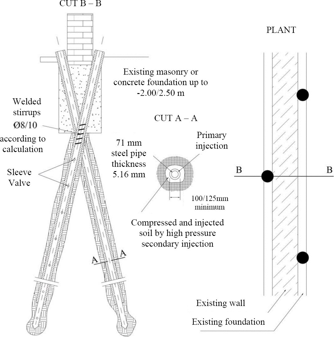
These elements were introduced sub-vertically through the elevation masonry, with an angle of attack such that allows the micropiles to cross the support base in its middle third. In this way, it was avoided having to execute a corbel header to underpin the wall. The transfer of loads from the wall to the pile is developed through friction between the masonry bricks and the material that fills the space between the perforated wall and the steel shaft of the micropile.
6.2 Proposal for underpinning interior walls
The arrangement of the micropiles to materialize the underpinning of the walls is carried out in three-bolillos (Figure 11). The number of micropiles to be used is determined by the load the wall receives and the load capacity of the micropile. Table 1 shows the calculation parameters of the micropiles that then allowed us to determine the amount needed for the underpinning of each wall.
Figure 11. Diagram of support of interior walls in sub-vertical micropiles.
Table 1. Calculation parameters of each micropile in contact with masonry.
| Material | Diameter [mm] |
Diam. Perforation [mm] |
Frictional length [mm] |
Frictional strength [kg/cm2] |
Load Capacity [tn] |
| Grouting | |||||
| Steel | 73 | 125 | 100 | 4 | 6,50 |
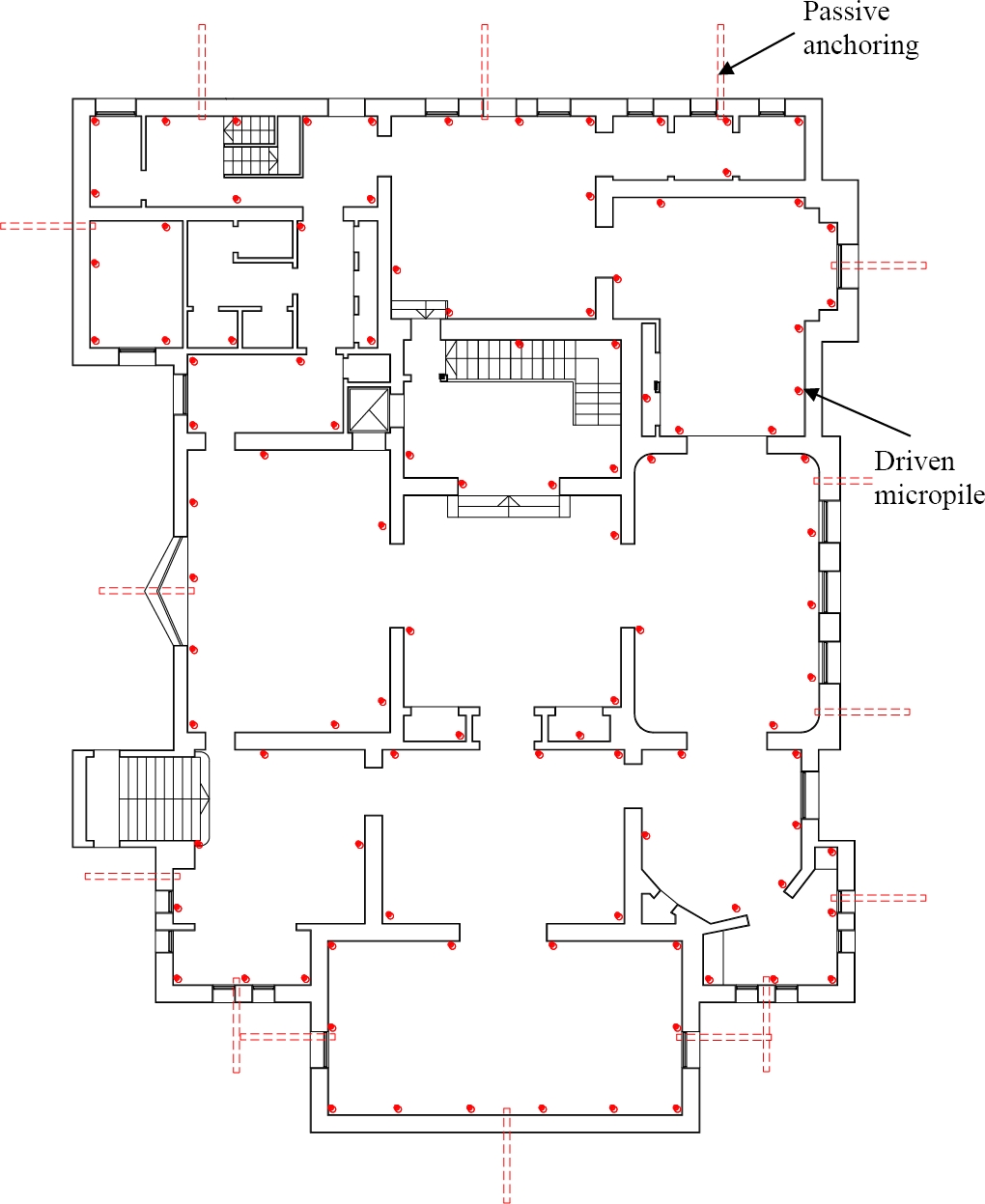
The location of the elements is detailed in the Basement Plan (Figure 12).
Figure 12. Diagram of the subsoil with the proposed location of the driven micropiles.
First of all, before designing the underpin, the load analysis of the most loaded interior wall was carried out, determining the number of micropiles to be distributed under each wall. Likewise, the load analysis of the most loaded perimeter wall was also carried out. These have the particularity that it is only possible to top them by means of micropiles from a single side, causing the load to be eccentric, so they had to be anchored to balance this eccentricity. The latter situation is discussed in detail below.
To determine the load transferred by the walls, first, the load analysis of mezzanine and non- accessible roof slabs was carried out (Table 2). The load analyses of the most loaded interior and exterior walls are presented in Table 3.
Table 2. Slab load analysis.
| Item | Mezzanine Slab | Non-Accessible Roof Slab |
| Load [tn/m2] | Load [tn/m2] | |
| Forged | 0.33 | 0.33 |
| Floor | 0.19 | 0.19 |
| Ceiling | 0.03 | 0.03 |
| Total Dead Load | 0,55 | 0,55 |
| Useful Overload | 0.20 | 0.10 |
| Total Slab Load | 0.75 | 0.65 |
Table 3. Wall load analysis.
| Item | Interior Wall | Muro Perimetral |
| Load [tn/m] | Load [tn/m] | |
| Slabs on SS | 3.84 | 2.22 |
| Slabs on PB | 3.84 | 2.22 |
| Slabs on PA | 3.32 | 1.76 |
| Wall | 11.00 | 11.96 |
| Total Wall Load | 22.00 | 17.80 |
During the execution, and in order to cross the wall avoiding vibrations due to driving, a hole of 120 mm in diameter was first drilled with a diamond crown, until it crossed the support base. At that moment, the crown was removed and the micropile was introduced until it made contact with the underlying soil, to just begin the driving process. In the case of the interior BA walls, the piles alternate on either side of each wall, with a "cot leg" scheme, as shown in Figure 11.
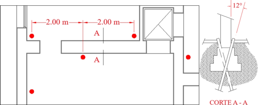
Figure 13 shows a detail with the approximate separation between micropiles, arranged on both sides of the interior walls, and a section with the detail of their location in relation to the existing foundation.
Figure 13. Detail of the arrangement and separation of micropiles in interior walls, along with a cut showing the link with the foundation masonry.
Once the foundation horizon was reached, the bulb and stem were injected with primary injection of gravity-cast H-17 cement slurry, and secondary injection of H-21 at 10 kg/cm2 of pressure (consumption was around 40 liters for primary injection and 160 liters for secondary injection). Prior to injection, hydraulic seals were placed in the center of the pile to prevent the return of the grout to the surface.
In the specific sectors in which voids or sinkholes were noticed under the floor during the execution of the underpinning piling, they were filled by injections of soil cement in proportions of 1:7 (binder, earth), with fluid consistency to ensure the correct filling of all spaces and interstices, without the injection pressure exceeding the value of 2 kg/cm2.
6.3 Proposal for underpinning exterior walls.
For the outer (perimeter) walls, work was done only from the inner side of the BA, and to balance the moments generated by the pile line, sub-horizontal tensioners were executed across the wall, which act as passive anchor reins to balance the eccentricity in the transfer of loads to the sub- vertical micropiles. These sub-horizontal elements do not exceed the limits of the property (Municipal Line) and have a guaranteed minimum load capacity of 10 tons for each unit, as required by calculations. Likewise, and prior to its execution, the absence of buried infrastructure that could be damaged during the works was verified. It is noteworthy that these turnbuckles are pre- excavated before the reinforcement is inserted.
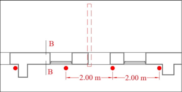
Based on the analysis of the load of the outer wall and the bearing capacity of each micropile, the underpinning project was developed, the details of which are presented in Figure 14. The sub- vertical arrangement of the driven micropiles, crossing the alignment of the exterior walls only from the inside of the subsoil, generates a horizontal thrust on the underpinning structure that must be balanced in part, by means of the frictional resistance developed in the wall-floor interface, and the surplus, from the incorporation of a passive sub-horizontal anchor arranged towards the perimeter retreat of the palace. The diagram of loads involved in the wall is shown in Figure 15, from which it is feasible to determine the value of the load to be balanced by means of the proposed passive anchorage.
Figure 14. Detail of the arrangement and separation of micropiles in exterior walls, with the tentative location of the passive balance anchors.
Figure 15. Section B-B, shown in Figure 14, showing the connection with the foundation masonry and the arrangement of the passive anchorage.
The magnitude of the horizontal thrust responds to the horizontal component of the internal stress in the micropile. The frictional resistance at the floor-wall interface balances part of the thrust, resorting to the execution of passive anchors to balance the remaining thrust. The separation of the anchors depends, in addition to the sum of the unbalanced thrusts in each perimeter micropile, on the ability of the wall to be able to transfer these unbalanced thrusts to the anchorage. Each passive anchor was considered to absorb up to 4 micropiles, spaced 2m apart.
From the loads detailed in Figure 15, the horizontal force balance equation (1) is proposed, from which the value of the anchor stress is delineated, by micropile.
| (1) |
From (1) it is determined that:
| (2) |
From Table 1, assuming a guaranteed contact surface at the micropile-grouting interface of 30 cm of development, the maximum permissible load to be transferred to each micropile will be 20 tons. On the other hand, the coefficient of friction between the tie and the ground is of the order of 0.24.
This last value allows us to determine the value of the friction at the interface, taking the load of the least loaded wall (15 tons) conservatively.
From (2):
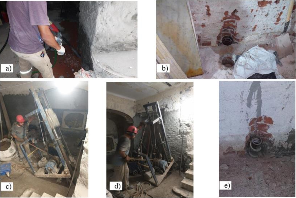
The thrust to balance by means of passive anchors is the equivalent of 4 micropiles. Consequently, the passive anchor will have to be designed to absorb 10 tonnes. The proposed separation of 2.00m between micropiles is reasonable and allows us to infer that the load transferred to each micropile is approximately 40 tons. Because each pile has a load capacity of around 20 tons, the load not absorbed by the micropiles will continue to be resisted by the supporting soil. In this sense, it is considered to be low and compatible with the carrying capacity of the same, so that it is sufficient for the cessation of settlements. Figure 16 shows, by means of a photographic sequence, the driving procedure of a metal micropile.
Figure 16. Detail of the intervention procedure. a) Image of diamond crown drilling. b) Photograph of the holes drilled in the masonry up to the pre-existing floor horizon. c) Photograph taken during the mechanical driving process of the micropile. (d) Photograph taken during the driving of a micropile. e) Image of the upper end of the Manessmann tube, driven, with welded abutments to increase the frictional surface against the sub-pressure slab to be executed.
7. VERIFICATION OF RESULTS
To ensure the minimum load capacity of 20 tons per pile, a load test was carried out on a vertical micropile. To do this, three identical piles were driven into the building's garden: the two external ones support the reactive mechanism by traction, consisting of a large metal beam, under which a hydraulic jack with a capacity of 100 tons was placed, driven by an independent manual hydraulic power plant, linked to the jack with high-pressure hoses.
The metal beam compresses the central micropile to be tested through the hydraulic jack. Once the reactive frame was positioned, the measuring elements (fleximeters) were placed to read the deformations of the latter, arranged at 120º from each other in order to materialize the reference plane. These comparators were placed with 0.80 m long arms attached to the head of the micropile in order to avoid possible influences due to deformation of the soil around it. The accuracy of the instruments used is 0.01 mm.
Upward (charging) and downward (unloading) charging cycles were performed. The ascending cycles were carried out with loads of 5.00 tons each until reaching a final maximum load of 45.00 tons, while the descending cycles were executed in steps of 10.00 tons until the tested element was completely discharged. In each cycle, both charging and unloading, instantaneous and delayed strain measurements were made for 30 minutes, before increasing the load to the next step.
Every 10 tons, the system is unloaded and residual strain readings are taken, which is the parameter to be checked, before starting a new loading cycle. The final deformation must not exceed 10% of the pile diameter (125 mm), i.e. the maximum permissible residual deformation cannot be greater than 12.5 mm, for the requested service load of 20 tons.
Table 4 shows the aforementioned values, clarifying that once the load exceeded 45 tons, a tensor of the reactive frame was cut, and the test was completed.
Table 4. Load test results sheet.
| Reading Manom. (kg/cm2) |
Load Applied (tn) |
ReadingC. 1 (N) (mm) |
ReadingC. 2 (W) (mm) |
ReadingC. 3 (S) (mm) |
Observ. Prompt reading. (mm) | Deform. plastic (mm) |
| First Charge Cycle (accommodates Reactive frame) |
||||||
| 0,00 | 0,00 | 9,26 | 3,00 | 3,78 | Initial reading 4,34 | 0,00 |
| 25,00 | 5,00 | 12,18 | 2,32 | 2,45 | 5,65 | 1,31 |
| 50,00 | 10,00 | 13,85 | 2,56 | 2,45 | 6,28 | 1,94 |
| Discharge | ||||||
| 0,00 | 0,00 | 9,54 | 3,22 | 3,57 | 5,44 | 1,10 |
| Segundo ciclo de carga | ||||||
| 0,00 | 0,00 | 9,54 | 3,22 | 3,57 | Initial reading 5,44 | 0,00 |
| 25,00 | 5,00 | 12,48 | 2,63 | 2,56 | 5,89 | 0,45 |
| 50,00 | 10,00 | 13,40 | 2,67 | 2,37 | 6,14 | 0,70 |
| 75,00 | 15,00 | 15,55 | 4,00 | 1,89 | 7,14 | 1,70 |
| 100,00 | 20,00 | 19,40 | 6,03 | 1,67 | 9,03 | 3,59 |
| Discharge | ||||||
| 50,00 | 10,00 | 16,90 | 6,02 | 1,41 | 8,11 | 2,67 |
| 0,00 | 0,00 | 11,93 | 4,95 | 3,42 | 6,76 | 1,32 |
| Tercer Ciclo de carga | ||||||
| 0,00 | 0,00 | 11,93 | 4,95 | 3,42 | Initial reading 6,76 | 0,00 |
| 50,00 | 10,00 | 16,35 | 5,32 | 1,48 | 7,71 | 0,95 |
| 100,00 | 20,00 | 19,82 | 6,40 | 1,68 | 9,30 | 2,54 |
| 125,00 | 25,00 | 24,00 | 8,00 | 2,46 | 11,48 | 4,72 |
| 150,00 | 30,00 | 26,32 | 9,60 | 3,62 | 13,18 | 6,42 |
| 175,00 | 35,00 | 30,45 | 10,85 | 5,66 | 15,65 | 8,89 |
| 200,00 | 40,00 | 31,82 | 10,60 | 7,00 | 16,47 | 9,71 |
| 225,00 | 45,00 | Cut this tensioner to 45 tons | ||||
| Discharge | ||||||
| 125,00 | 25,00 | 29,30 | 9,85 | 6,75 | 15,30 | 8,45 |
| 50,00 | 10,00 | 26,52 | 8,23 | 4,14 | 13,83 | 7,07 |
| 0,00 | 0,00 | 19,30 | 8,10 | 3,95 | 10,45 | 3,69 |
Figures 17, 18 and 19 show the Load-Strain plots for each cycle.
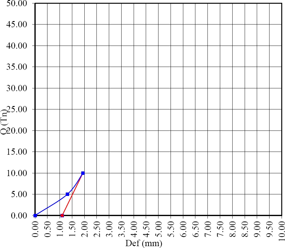
Figure 17. Load-strain graph of the 1st loading cycle (10 tn).
Figure 18. Load-strain graph of the 2nd loading cycle (25 tn).
Figure 19. Load-deformation graph of the 3rd loading cycle (45 tn).
Figures 17 and 18 show a quasi-linear behavior of the soil requested by the micropile, both in load and discharge, warning that, due to the level of deformations reached, there is a modification of the cemented microstructure of the silt, causing plastic deformations (permanent) but compatible with the limit established for the residual values of settlements. Figure 19 shows a clear bilinear behavior, typical of cemented silt, in which the slope of the load-settlement curve changes from the applied load of 30 tons (Capdevila, 2008). After the tensioner breaks, the discharge is carried out, reaching an internal residual settlement at the limit value.
8. CONCLUSIONS
Driven micropiles are an alternative to traditional in-situ concreting ones, especially indicated when foundations must be undepined in existing buildings of heritage value, where it is advisable to minimize the breakage of floors or walls as well as to avoid (or at least reduce) the volume of excavations and subsequent transfer of earth to a container, due to the additional cost and risk of damage that this operation implies due to collisions or friction of the forklift against walls, carpentry, etc.
Its load capacity depends on the diameter of the tube used and the type and pressure of injection, and there is the possibility of executing variable selective repetitive injections (IRS) at each depth, when heterogeneous strata are crossed, in which case seals are placed that limit the injection only to the preset layer. In this way, high load-bearing capacities can be achieved, while also avoiding the execution of transfer elements such as wall beams.
In the above case, for a load (45 tonnes) that is 250% higher than the service load (13 tonnes), the deformation of the element was around 30% of the maximum permissible by regulation.
Finally, and as the mass of the piling machine has the same weight and drop height required by regulations for the execution of SPT tests, the jacking of each micropile makes it possible to verify point by point any variations or heterogeneities in the expected lithological profile.
9. REFERENCES
Capdevila, J. A. (2008). “Comportamiento Tensión-Deformación del Loess del Centro de Argentina en Campo y Laboratorio: Influencia de los Parámetros Estructurales”. 1º Ed. 2009. Tesis Doctoral. Universidad Nacional de Córdoba. ISBN: 978-987-05-6839-1
Cisneros, J. M., Gil, H. A., de Prada, J. D., Degioanni, A. J., Cantero, G. A., Giayetto, O., Ioele, J., Madoery, O. A., Masino, A., Rosa, J. (2014). “Estado actual, pronósticos y propuestas de control de inundaciones en el centro-este de la provincia de Córdoba”. Servicio de Conservación y Ordenamiento de Tierras (SECYOT). Facultad de Agronomía y Veterinaria. Universidad Nacional de Río Cuarto. Recuperado de URL: http://www.todoagro.com.ar/documentos/2014/Informe_Inundacion_SeCyOT_2014.pdf.
Francisca, F. M. (2007). “Evaluating the constrained modulus and collapsibility of loess from standard penetration test”. ASCE International Journal of Geomechanics. 7(4):7-10. ISSN 1532-3641. https://doi.org/10.1061/(ASCE)1532-3641(2007)7:4(307)
Gómez, M. L., Blarasin, M., Cabrera, A., y Matteoda, E. (2006). “Variaciones de nivel freático y contaminación del acuífero en la zona de Coronel Moldes, Córdoba”. 1º Congreso Internacional sobre Gestión y Tratamiento Integral del Agua. Córdoba, Argentina.
Videla Mensegue, H. R., Degioanni, A. J., y Cisneros, J. M. (2015). “Estimating shallow water table contribution to soybean water use in Argentina”. European Scientific Journal. 11(14): 23-40. ISSN: 1857-7881 (Print), e - ISSN 1857- 7431.