![]()
| Basic Research | https://doi.org/10.21041/ra.v14i1.715 |
Pathological study using ultrasound tests applied to structures under construction
Estudio patológico empleando ensayos de ultrasonido aplicado a estructuras en construcción
Estudo patológico por meio de testes de ultrassom aplicados a estruturas em construção
1 Steel Concrete Test, La Paz, Bolivia.
*Contact author: gustavo.ergueta@gmail.com
Received: 04/11/2023
Revised: 19/12/2023
Accepted: 22/12/2023
Published: 01/01/2024
| Cite as: Ergueta, G. A.; Quino, M. V. (2024), “Estudio patológico empleando ensayos de ultrasonido aplicado a estructuras en construcción”, Revista ALCONPAT, 14 (1), pp. 82 - 95, DOI: https://doi.org/10.21041/ra.v14i1.715 |
Abstract
The study discuss the results of the evaluation of reinforced concrete structures using non-destructive testing (NDT) based on ultrasonic pulse velocity (UPV) with the objective of determining the integrity and uniformity of the concrete, as well as detecting possible anomalies caused during construction or by external factors. The results showed the distribution of damage in a structure affected by fire, the measurement of cracking depth in a concrete element and the uniformity in different structural components, which subsequently allowed the development of the corresponding structural rehabilitation procedure. The study demonstrates the effectiveness of NDT and UPV in the evaluation of reinforced concrete structures, allowing immediate repair and rehabilitation decisions to be made.
Keywords: non-destructive testing; ultrasonic pulse velocity; anomalies, rehabilitation; concrete.
1. INTRODUCTION
Within the pathological study of reinforced concrete structures, the use of non-destructive testing (NDT) has become a useful tool to assess the quality and condition of buildings. Technological advances in this field have made it possible to obtain reliable results practically in real time, through the use of equipment that already incorporates artificial intelligence (AI) for data processing.
The results of these studies and the detection of anomalies at an early age in the structures, before visible damage is detected, make it possible to significantly reduce repair costs and increase their useful life, reducing the deterioration of the concrete and the risk to the integrity of the structure.
The origin of these anomalies can occur during the construction stage of the structure due to insufficient control, or during the useful life of the structure, due to the lack of an adequate maintenance plan. For this reason, structural evaluation has become a good practice to ensure the safety and stability of buildings.
Within NDT, the ultrasonic pulse velocity test (UPV) can be used to determine the uniformity of concrete. This method is based on the fact that a change in the UPV measured across the element is fundamentally related to a change in the elastic modulus of the concrete. This method allows information to be obtained over the entire thickness of the element as opposed to other methods that only allow evaluation of the surface. However, special consideration must be given to the heterogeneity of the concrete.
An adequate use of multiple equipment can avoid distortions in the data collection of the UPV values. Also, the sectors to be evaluated should be previously analyzed with a rebar detector to identify the areas with presence of steel reinforcement.
This work seeks to share the results obtained by applying different UPV methods applied to real cases, with the objective of determining the level of damage in reinforced concrete structures evaluated during the construction stage.
2. EVALUATION OF REINFORCED CONCRETE STRUCTURES THROUGH UPV TESTS
The main objective of the evaluations is related to the determination of the degree of integrity and uniformity of the concrete affected by external factors originated in the construction stage or external actions that may reduce its mechanical characteristics.
The possibility of having this information during the execution of a work allows immediate decisions to be made related to the restitution of damaged elements or their structural rehabilitation. For the proposed cases, all the structures were rehabilitated after their evaluation, since the results obtained confirmed that the existing damage once the structure was rehabilitated did not affect its structural capacity.
The methodology used to collect UPV data, as well as the reference documents for the analysis of results, is described in this work.
As established in section 5.2 of the ASTM C 597-02 standard, the UPV test is valid to evaluate the uniformity and relative quality of concrete, as well as to detect voids and cracks in structures. In addition, it can be used to evaluate the effectiveness of repaired cracks. It is also useful to indicate changes in concrete properties and in the evaluation of structures, which allows estimating the severity of deterioration caused by cracking.
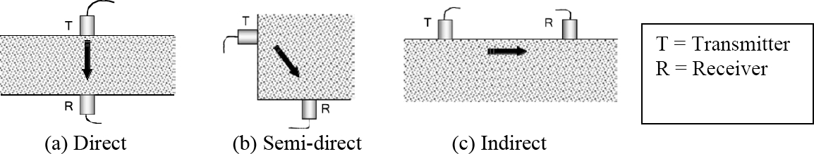
For the evaluation using UPV test, three possible configurations of the transducers are used, as described by Naik, Malhotra and Popovics (2004): direct transmission, Figure 1(a). semi-direct transmission, Figure 1(b); and indirect or surface transmission, Figure 1(c).
Figure 1. UPV measurement settings. (a) Direct method. (b) Semi-direct method. (c) Surface indirect method. Naik, Malhotra y Popovics (2004)
The direct transmission method is the most desirable and the most satisfactory, because with this arrangement the maximum energy of the impulse is transmitted and received. The semi-direct transmission method can also be used quite satisfactorily; however, care must be taken that the transducers are not too far apart; Otherwise, the transmitted pulse may be attenuated and a pulse signal may not be detected. This method is useful to avoid reinforcement concentrations. The indirect or surface transmission method is the least satisfactory because the amplitude of the received signal is significantly smaller than that received by the direct transmission method. This method is also more error prone and a special procedure may be necessary to determine the pulse rate.
Based on the above, a widely used classification of concrete according to its UPV is the one developed by Feldman. (1977).
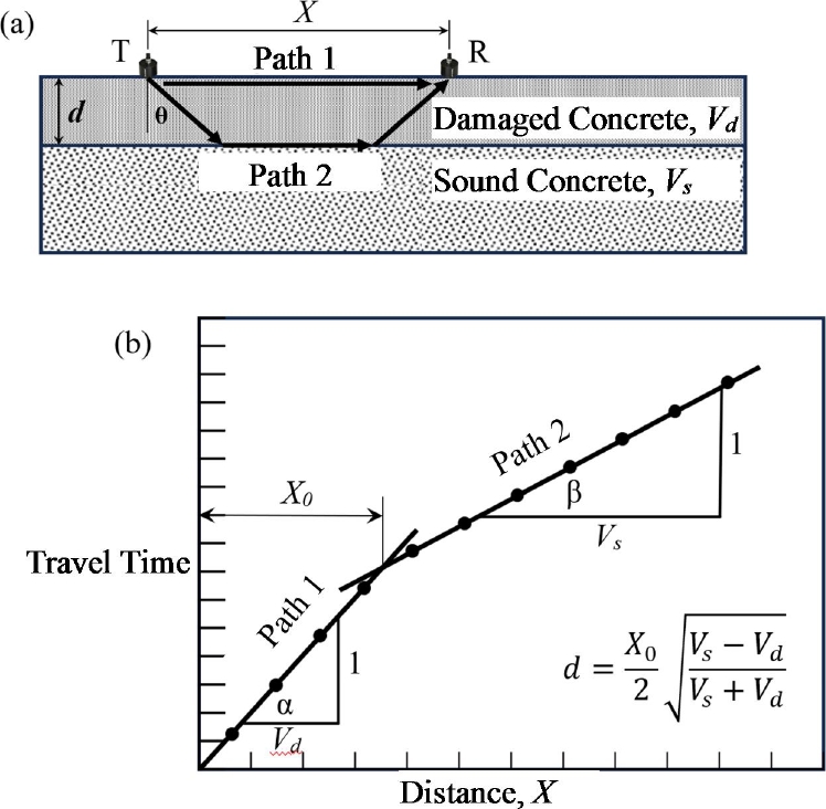
Section 3.2.1 of ACI 228.2R-13 indicates that UPV data collection through indirect measurements can be used to measure the depth of a surface layer damaged by fire or freezing (Figure 2), because it has a lower wave velocity than the underlying sound concrete.
Figure 2. (a) Wave paths for ultrasonic testing on surface of concrete having damaged surface layer. (b) travel time as a function of distance between transmitter and receiver. Taken from ACI 228.2R-13.
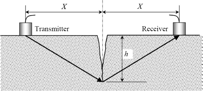
Likewise, Naik, Malhotra and Popovics (2004) state that the UPV method is effective for characterizing surface cracks (Figure 3 and equation 1):
Figure 3. Determination of cracking depth. (Naik, Malhotra y Popovics 2004).
| (1) |
2.1 Equipment used
The equipment used for the evaluations mentioned above are:
2.1.1 Rebar reinforcement detector
Rebar reinforcement detection was carried out using a Proceq Profometer 650 AI computerized rebar detector with the ability to detect steel reinforcement in concrete and estimate its diameter using eddy current pulse induction technology.
2.1.2 Ultrasound equipment
The UPV data collection were taken using Proceq Pundit 200 equipment, which allows the evaluation of the uniformity of the concrete, as well as the determination of the cracking depth using longitudinal wave transducers.
3. RESULTS USING UPV IN THE EVALUATION OF STRUCTURES
The three practical cases of evaluations of reinforced concrete structures through UPV tests were carried out in different projects in La Paz - Bolivia; projects that were in the construction stage.
3.1 Evaluation of a structure subjected to the action of fire
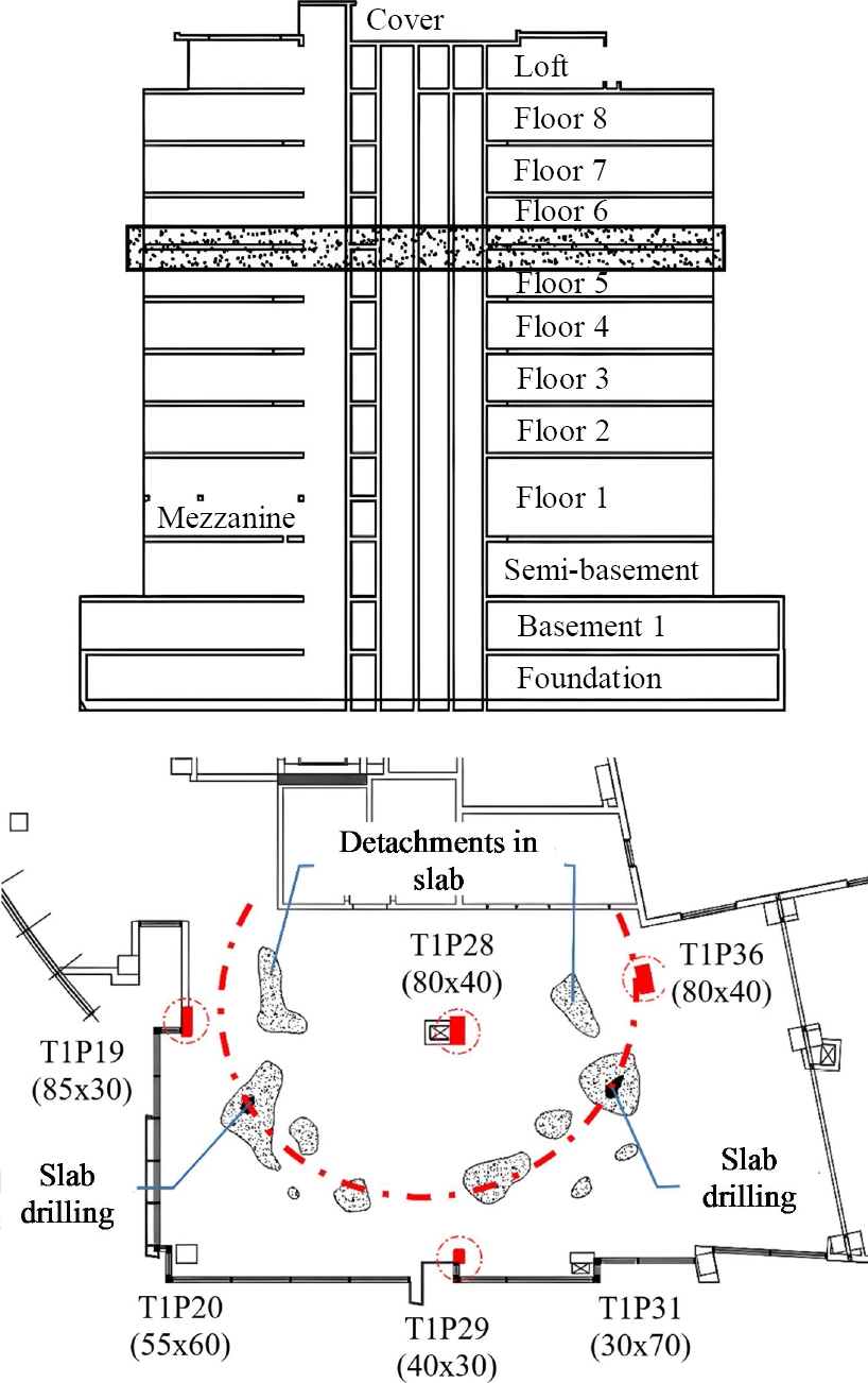
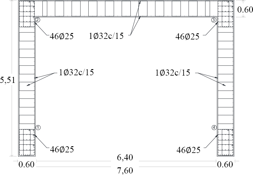
The structure corresponds to a 13-story building as shown in Figure 4:
Figure 4. Building layout and slab damage.
Figure 4 shows the distribution of damage in the slab as a result of the fire action, presenting a radial configuration with an approximate center at column T1P28, this situation confirms the fact that the column and abacus corresponding to this location are the elements with the greatest surface damage, and elements T1P20 and T1P31 do not present visual damage because they are located at a greater distance.
Direct and indirect UPV data collection was taken in the most affected column (T1P28) in order to evaluate the uniformity of the concrete throughout the thickness of the element, as well as to determine the thickness of the concrete damaged by the action of the fire.
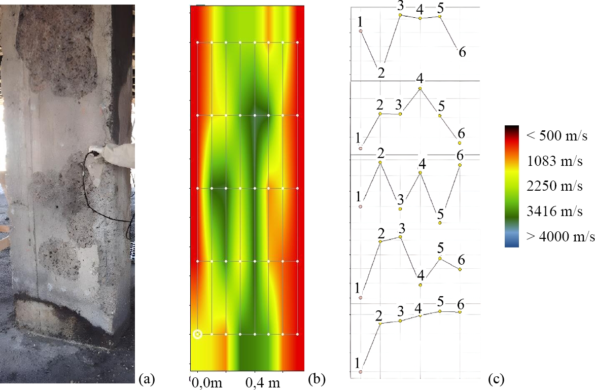
Figure 5(a) shows the state of the column after the fire, Figure 5(b) is the representation of the UPV at the major face through the entire thickness of the column, and Figure 5(c) corresponds to the linear velocity data at the major faces of the column.
Figure 5. T128 column condition and UPV values.
The maximum value of the damaged thickness was determined by analyzing a series of UPV data as described in ACI 228.2R-13, shown in Figure 2.
With the maximum value of the damaged thickness and its correlation with the linear velocity Figure 5(c), the damaged thickness at each level of the element was determined.
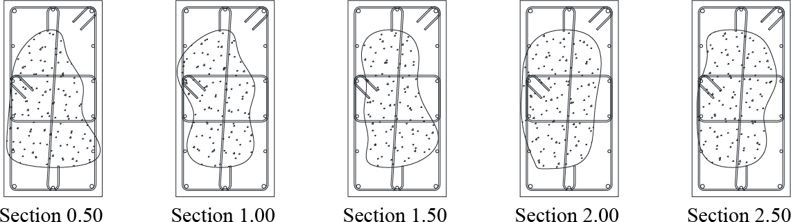
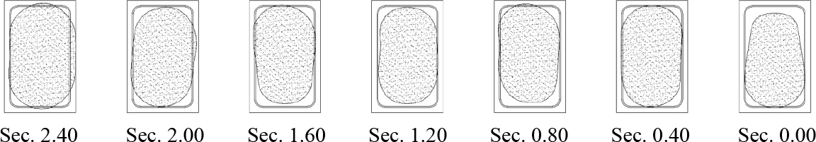
Using the data taken, the cross sections at different levels of the resulting uniform portion are presented, discounting the thickness with the lowest velocity corresponding to the damaged layer:
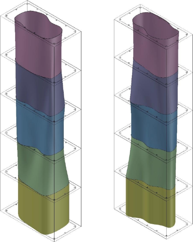
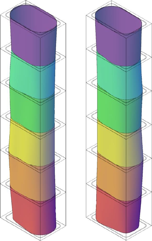
These results are represented in a three-dimensional form (Figure 7), achieving a complete appreciation of the element, thus allowing the elaboration of the structural repair plan.
Figure 6. Cross section of the uniform portion of the column
Figure 7. Uniform portion of the column in three-dimensional format.
3.2 Uniformity evaluation of reinforced concrete elements.
The evaluated elements correspond to structural components of a reinforced concrete building such as columns, beams and walls, which presented different anomalies perceived at the moment of removing the formwork, such as: presence of surface voids, plastic settlement, segregation and exposed reinforcement.
For this document, we limited ourselves to the analysis of the column with the most severe damage, carrying out the study before and after the corresponding structural rehabilitation process had been carried out.
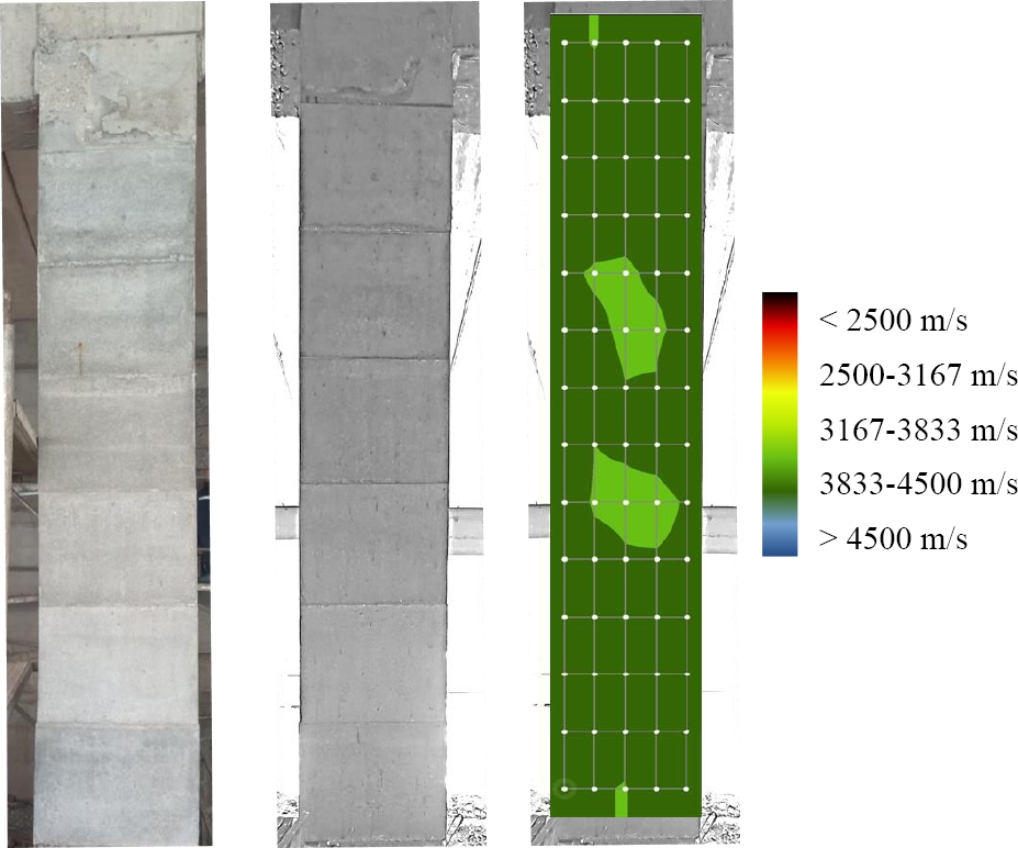
In Figure 8, most of the surface of the largest dimension of the element presents high values of ultrasonic pulse, corresponding to a concrete with "good" classification, as established in Table 1. However, there are sectors with low ultrasonic values, corresponding to a concrete with mainly "questionable" classification, with some localized points with a "poor" classification.
Figure 8. Anomalies in column and UPV map, before rehabilitation.
Table 1. Classification of concrete according to its ultrasonic velocity CBD-187 Non-Destructive Testing of Concrete
| CLASSIFICATION OF CONCRETE ACCORDING TO ITS UPV | |
| Ultrasonic velocity (m/s) | Classification of concrete |
| V > 4575 | Excellent |
| 4575 > V > 3660 | Good |
| 3660 > V > 3050 | Questionable |
| 3050 > V > 2135 | Poor |
| V < 2135 | Very poor |
Considering that most of the element has a "good" concrete classification, direct and indirect measurements were made to determine the thickness of the segregated concrete, obtaining the following sections of the uniform concrete core, Figure 9:
Figure 9. Cross section of the uniform portion of the column
Figure 10 shows a fairly close representation of the actual situation of the column.
Figure 10. Uniform portion of the column.
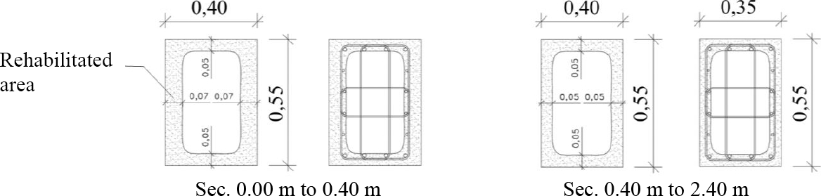
The middle healthy section sectors of the column and the rehabilitated thickness are shown in Figure 11 once the defective material has been removed.:
Figure 11. Cross section of the column after rehabilitation.
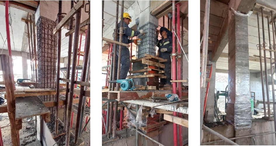
During the structural rehabilitation work, it is evident the precision reached in the pathology studies, being the middle part of the front face and the lower part of the back face the most damaged sectors and with the greatest loss of section, Figure 12.
Figure 12. Structural rehabilitation process.
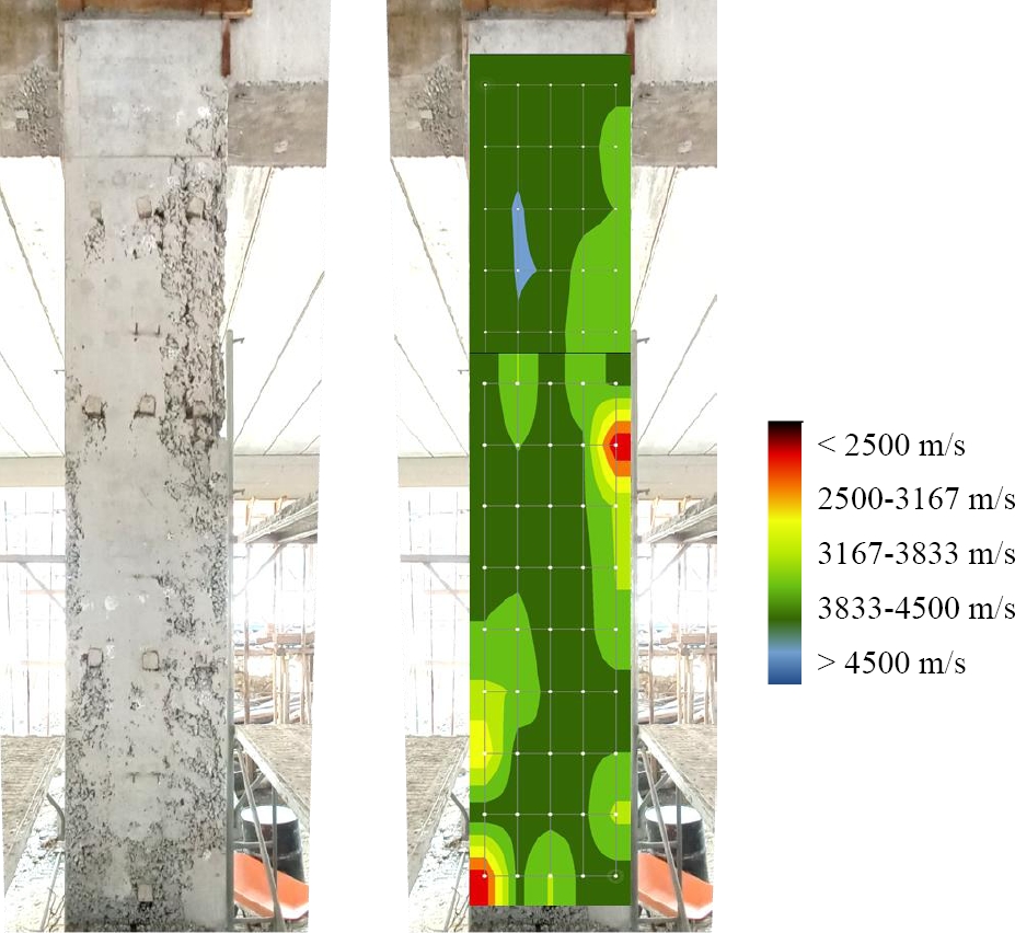
Once the element has been rehabilitated, it can be seen that before rehabilitation, the points with questionable classification had an average pulse velocity of 3496 m/s, after rehabilitation, the average pulse velocity is 3933 m/s, achieving an improvement in the uniformity of these points of approximately 13%.
In the case of the points with poor classification, before rehabilitation, they had an average pulse velocity of 2419 m/s, after rehabilitation, the average pulse velocity is 3950 m/s, achieving an improvement in the uniformity of those points of approximately 63%. See Figure 13.
Figure 13. Column condition and UPV map, after rehabilitation.
3.1 Integrity assessment and cracking analysis of a reinforced concrete element
The structure corresponds to a reinforced concrete core as shown in the following scheme, see Figure 14:
Figure 14. Reinforced concrete core.
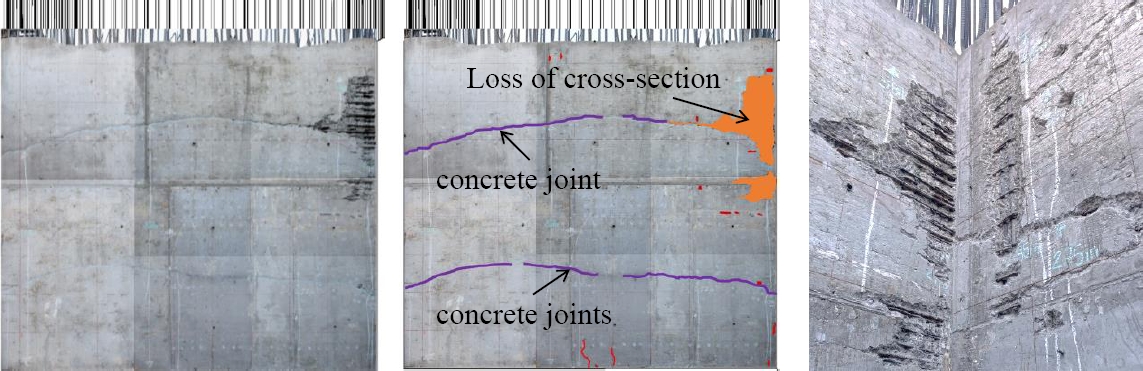
In several sectors of the element, the presence of anomalies of different origin, produced in the first hours of concreting, and perceived at the moment of removing the formwork, was observed. The anomalies present were: plastic settlement, plastic shrinkage, segregation, presence of surface voids, exposed reinforcement and cold concrete joints.
In the specific case presented in this work, the cold joints produced between concreting levels and the cracks due to the lack of continuity on the surface of the element were analyzed, see Figure 15.
Figure 15. Core sidewall anomalies.
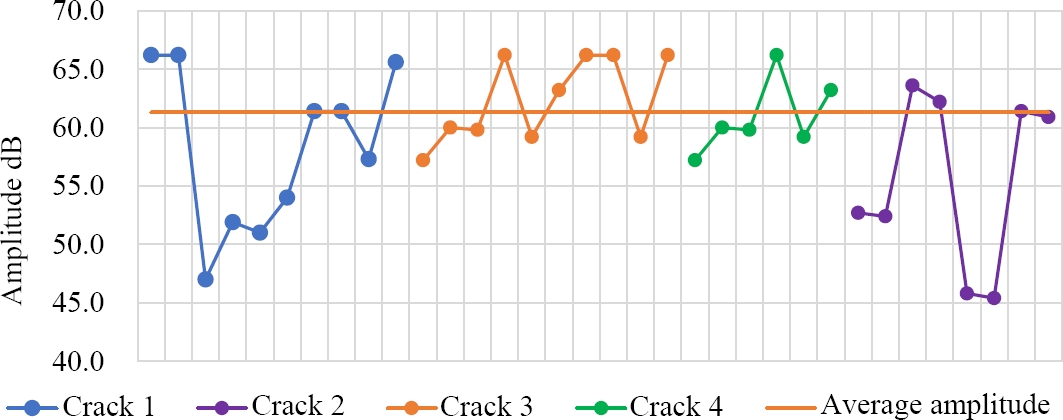
Once the UPV data were taken along the longitudinal axis of the cracks, it was determined that the maximum cracking depth is 14.7 cm and the minimum is 2.9 cm, with an average value of 7.0 cm; this value can be adopted as a reference for the rest of the cracks.
Once the element was rehabilitated through sealing by injecting the cracks with epoxy resin, the repaired element was analyzed according to Souza and Pinto (2020), who explain that the ultrasonic waveform represented by the amplitude indicates changes in the stress wave due to reflection and refraction that occurs at any interface of materials with different acoustic properties. That is, a concrete-epoxy interface would alter the waveform, but not the velocity. Therefore, by analyzing the complete waveform and its relationship to the amplitude, it can be evaluated whether the crack was properly repaired.
In this sense, the average wave amplitude of the element was determined and compared with the wave amplitude of each crack evaluated along its longitudinal axis. In Figure 16 it can be seen that the points with an amplitude above the mean value of the element would have been adequately sealed and those below this value would have been partially sealed, this may be due, among other aspects, to the fluidity of the epoxy resin that normally allows sealing cracks greater than 0.5 (mm) thick.
Figure 16. Wave amplitude in cracks.
4. RESULTS DISCUSSION
The results of the three cases demonstrate the feasibility of using NDT and UPV equipment for structural evaluation. These cases correspond to projects in the construction stage, which allows performing complementary tests, such as exploratory coves, to obtain an accurate interpretation of the data obtained in the tests.
The proper handling and experience of the operator in data collection are of great importance to obtain reliable results, as well as the correct interpretation and correlation with other complementary tests, as well as the inspection of the elements on site, which are essential to generate recommendations and procedures for structural rehabilitation, if necessary.
The determination with a good approximation of the damaged thickness or sound section of an element allows quick decisions to be made on site regarding its rehabilitation or restitution.
The analysis performed to determine the damaged thicknesses in the element studied had adequate levels of accuracy that were verified during the structural rehabilitation.
It is important to quantitatively evaluate a rehabilitated structural element to avoid subjective criteria that may affect decisions. This is clearly evidenced in the third case, where a 63% improvement in the uniformity of the most affected sectors was achieved.
In the analysis of a cracked element, the wave amplitude method allows generating satisfactory results at the moment of evaluating its rehabilitation.
The values obtained are in accordance with the values established in the reference documentation. In case of requiring reference values that reflect results with local materials, it is necessary to carry out investigations that provide adequate information, based on studies carried out in similar contexts.
5. CONCLUSIONS
The UPV tests are versatile for evaluating reinforced concrete structural elements. Proper operation of the equipment and interpretation of the results are essential to obtain important information, which in turn influences the generation of repair and structural reinforcement plans, adapted to specific needs.
Anomalies, such as segregation or voids formation, can arise during construction processes. It is important to analyze the particular conditions on the day when such processes were carried out. The analysis of this information allows the development of contingency plans to deal with past events.
It is important to take into account that, although undesired, these events may occur. Therefore, it is necessary to have evaluation plans through NDT to determine the actual conditions of the affected elements. This facilitates the development of the best structural repair procedures and also has an impact on the final repair schedules and costs.
NDT have experienced notable progress, driven by improvements in the technology used. In this regard, the use of software tools that include fully customizable inspection workflows facilitates the documentation of all information in one place through the application of AI, as well as allowing remote inspections to be performed.
6. REFERENCES
American Society for Testing and Materials (2002), ASTM C 597-02, Standard Test Method for Pulse Velocity Through Concrete.
American Concrete Institute (2013), Report on Nondestructive test Methods for Evaluation of Concrete in Structures, ACI 228, 2R-13. American Concrete Institute, EUA.
American Concrete Institute (2001), Control of Cracking of Concrete Structures, ACI 224R-01. American Concrete Institute, EUA.
American Concrete Institute (2014), Guide to Concrete Repair - Report by ACI Committee 546, ACI 546R-143. American Concrete Institute, EUA.
American Concrete Institute (2009), Surface Repair Using Form-and-Pour Techniques - Field Guide to Concrete Repair Application Procedures, ACI RAP Bulletin 4. American Concrete Institute, EUA.
Feldman, R.F. (1977), CBD 187 Non-Destructive Testing of Concrete, Canadian Building Digest, Division of Building Research, National Research Council Canada,
Malhotra, V. M., Carino, N. J. (2004), “Handbook on Nondestructive Testing of Concrete”, Boca Raton, Florida, USA, cap 8, pp 8-1 - 8-19
Souza, F. C., Pinto, R. C. A. (2020), Ultrasonic investigation on the effectiveness of crack repair in concrete. IBRACON Structures and Materials Journal.