![]()
| Basic Research | https://doi.org/10.21041/ra.v14i1.716 |
Modification of a metal structure due to change of use
Modificación de una estructura metálica por cambio de uso
Modificação de estrutura metálica para troca de uso
J. L. Gómez1,2, K. Klein1,2, G. Montiel2
1 Facultad de Arquitectura Urbanismo y Diseño, Universidad Nacional de Córdoba, Córdoba, Argentina.
2 Alconpat Argentina, Córdoba, Argentina.
*Contact author: ccp.cons316@gmail.com
Received: 05/11/2023
Revised: 16/12/2023
Accepted: 27/12/2023
Published: 01/01/2024
| Cite as: Gómez, J. L., Klein, K., Montiel, G. (2024), “Modification of a metal structure due to change of use”, Revista ALCONPAT, 14 (1), pp. 70 - 81, DOI: https://doi.org/10.21041/ra.v14i1.716 |
Abstract
The purpose of this work is to discuss the modifications made to a metal structure built in 1930, made up of triangular lattice beams supported on 60 cm thick walls and 14 interior metal columns to cover an area of 875 m2 that housed the activities of the central market in the city of Deán Funes. In the 1980s the municipal management proposed its recovery for new sports uses, presenting the structural challenge of eliminating intermediate supports. The project and construction date from that time, and for this reason it is discussed the validity of the concepts and solutions adopted, as well as the importance of a maintenance plan to guarantee the degree of safety of the work.
Keywords: structural design; steel; patrimony recovery.
1. INTRODUCTION
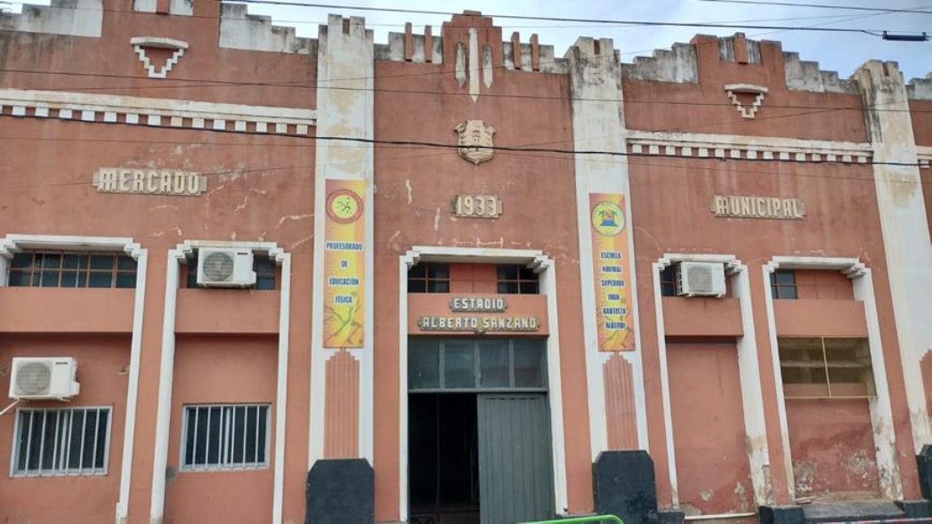
Dean Funes, capital of the department Ischilín, is a city located in the north west of the province of Cordoba. Its origins match with the expansión of the railway back in 1875. During the first years of the twentieth century, its most significant constructions, such as the Central Market (1930), that has an Art Decó style and it is located in front of the Market Plaza (figure 1), were built. During the following years, comercial activities were moved to the outskirts of the city due to the growth of population making the building to fall on a state of abandonment. In 1982, under the government of José Naveira Ferrandes, the building is decided to be restored and a new space for sports to be placed instead. Below, the structural proyect that made posible this new use, which was designed and built back then, and at present continues to be used with that purpose, will be developed.
Figure 1. Ex Central Market of Deán Funes.
2. ORIGINAL STRUCTURAL IDEA
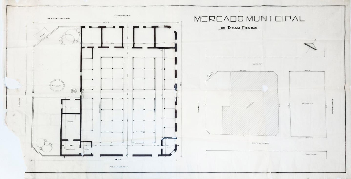
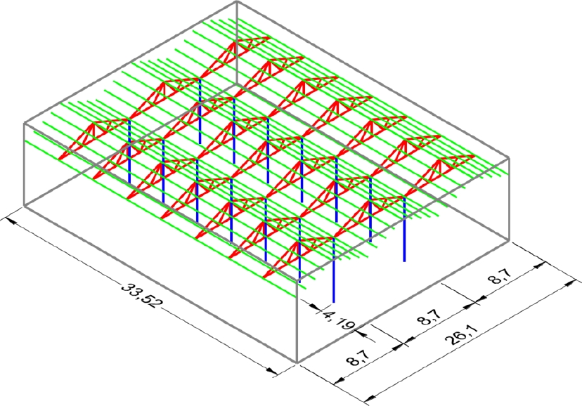
The original structural idea of the Market covered a surface of 875 m2 which includes 26,05 m width x 33,50 m lenght. The plane on top consisted of a series of three triangular metallic lattice beams with a 8,7 m span, which made 7 axis separated by 4,19 m. A series of steel belts that made the three-section, sheet, pitched roof were standing over the unión of the angles with a distance of 2,15 m and 2,200 m. The main beams rested on14 metallic columns and on its perimeter over a 60 cm width stone wall (figure 2 and figure 3)
Figure 2. Original Municipal Drawing
Figure 3. Original axionometric of the structure.
3. NEW STRUCTURAL IDEA
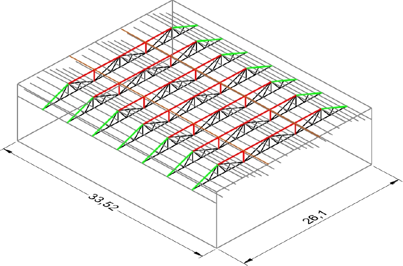
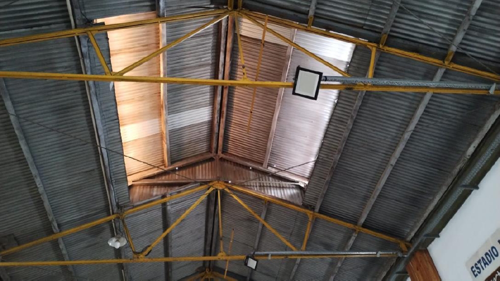
In order to have only one interior space free of bases, the new structure was proyected from one plain lattice beam of 1,80 m height, connecting the already existing ones, strengthening bars and adding new elements that allow the filling up of the 26,1 m of span.
To make the design of the new main beam it was necessary to build a new upper cord, which connected the metallic profiles of the existing bridgings, and two new posts matching the previous support that withstands the compression stresses and allows the lenght of the new cord’s bending to be reduced (figure 4).
Figura 4. Axonometric of the structural idea.
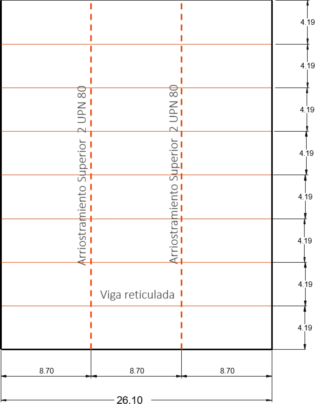
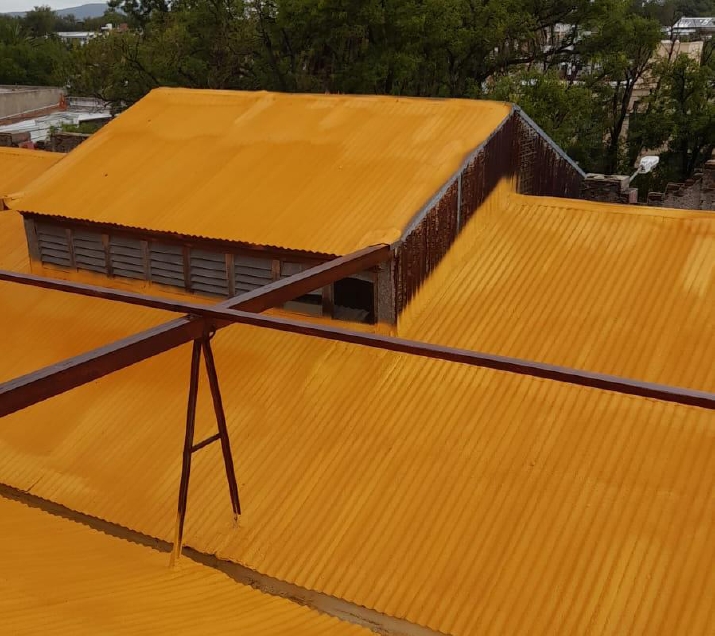
Equally, upper brace beams with two profiles UPN 80 were set in order to reinforce that concept and to avoid the lateral bending perpendicularly to the beam’s design (figure 5).
Figure 5. New exterior structure roof’s plan
On the other hand, both the inferior cord and some requested existing diagonals were reinforced in order to withstand the internal stresses of traction and compression from the evaluation of the new structural behaviour,
4. METHOD OF CALCULATION
Next, it will be presented the method of calculation based on the regulations and available tools at that time, but which have validity at present.
4.1 Analysis of loads
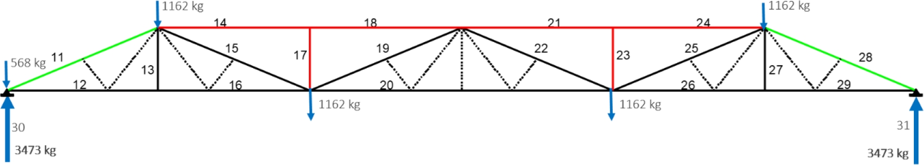
At first, an analysis per square meter was conducted to determin the magnitude of the punctual actions over the new lattice beam’s unión of its angles (figure 6).
Figure 6. Lattice beam with numbered bars, (nudos), and loads.
4.1.1 Analysis of loads per square meters
Corrugated sheet ------------------------------------- 10 kg/m2
Wooden beams --------------------------------------- 6 kg/m2
Lattice beam’s dead load--------------------------- 22 kg/m2
Superimposed usage -------------------------------- 25 kg/m2
TOTAL ----------------------------------------------- 63 kg/m2
4.1.2 Analysis of loads over girder’s union of its angles
Strut loads ----------63 kg/m2 x area of influence (4,19 x 2,2 m x 2) = 1162 kg
4.2 Determination of requests
To calculate the normal stresses, a PPlan program from the Taller de Investigación de Diseño Estructural (TIDE) of the Faculty of Architecture of the National University of Cordoba was used. At that momento, the coordenates that defined the beam’s geometry and the actions over itself were intriduced. As a result, the values of stresses in each unión of its angles which are summarized in the following table 1 were printed out.
Table 1. Requests and reactions.
| Bar | Normal stress (kg) |
| 11 | -7.598 Compression |
| 12 | 7.020 Tension |
| 13 | 0 |
| 14 | -11.233 Compression |
| 15 | 4.559 Tension |
| 16 | 7.020 Tension |
| 17 | -1.162 Compression |
| 18 | -11.233 Compression |
| 19 | -1.520 Compression |
| 20 | 12.637 Tension |
| 21 | -11.234 Compression |
| 22 | -1.519 Compression |
| 23 | -1.162 Compression |
| 24 | -11.234 Compression |
| 25 | 4.558 Tension |
| 26 | 7.022 Tension |
| 27 | -1 Compression |
| 28 | -7.600 Compression |
| 29 | -7.022 Compression |
| 30 | 3.474 Response |
| 31 | 3.474 Response |
4.3 Verification of general deformations
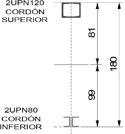
Considering the dimensions and analysis of the requests, the upper cord was premeasured with two profiles UPN 120 making a drawer-like section with an área of 27 cm2, and the inferior cord was premeasured with two matched UNP 100 profiles with an area of 22 cm2 (figure 7).
Figure 7. Compound section of the lattice beam.
From the analysis of the parameters that intervene in the determination of the maximum arrow, there was established the following data:
-Moment of inertia of the group J =392.769 cm4
- Load “q” 63 kg/m2 x 4,19 m = 260 kg/m
4.3.1 Calculation of the maximum arrow
| (1) |
| (2) |
4.3.2 Calculation of the admisible arrow
| (3) |
| (4) |
4.3.3 Comparison maximum arrow< admissible arrow
| (5) |
4.4 Sectional verification and proposals of the structure’s reinforces
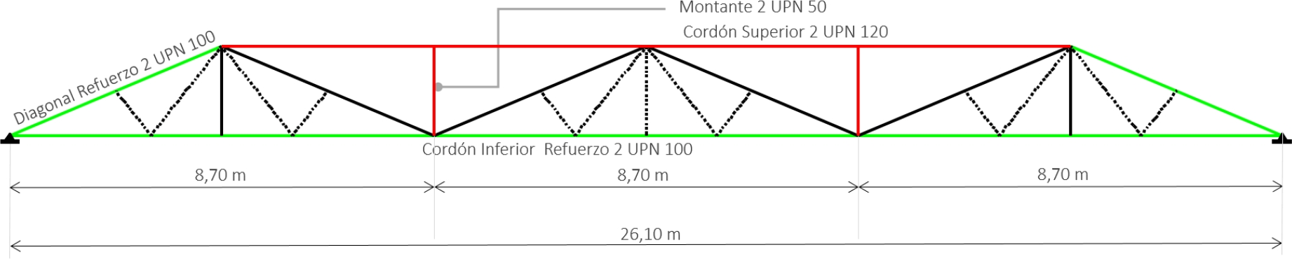
After the control of deformations, a sectional verification was conducted. First, regarding the new structural elements of the upper cord and the uprights. Second, regarding the resistance of the existing elements subdued to new efforts such as the inferior cord and the diagonals (figure 8).
Figure 8. Section of the lattice girder.
4.4.1 Upper Cord
As previously stated, the upper cord was carried out by the drawer-like section made of two UPN 120. The necessary data to verify the resistance is shown in table 2.
Tabla 2. Datos del cordón superior
| Bar 11 | 2 UPN 120 |
| Normal stress | 11.234 kg (compression) |
| Lenght | 440 cm |
| Moment of inertia Jx | 728 cm4 |
| Area of the group A | 34 cm2 |
Calculation of the minimun ratio turn
| (6) |
Calculation of the slenderness
| (7) |
Rate of the bending for steel F24
2,07
Calculation of the strain of work
| (8) |
4.4.2 Studs
The studs were defined by a drawer-like section as well, but made by two UPN 50. The necessary data to verify the resistance is shown in table 3.
| Bars 17/23 | 2 UPN 50 |
| Normal stress | 1.162 kg (compression) |
| Lenght | 180 cm |
| Moment of inertia Jx | 52,8 cm4 |
| Area of the group A | 14,24 cm2 |
Calculation of the minimun ratio turn
| (9) |
Calculation of the slenderness
| (10) |
Rate of the bending for steel F24
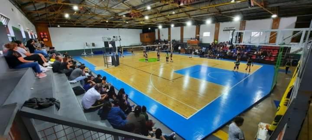
2,05 Calculation of the strain of work During the executive proyect, the studs were resolved to be made with two elements with the shape of an inverted “V” to fix the rainwater drainage system over the valley rafters (figure 9). Figure 9. Picture of the external structure 4.4.3 Inferior Cord A sole inferior cord was design to join the existing cords and to resist a máximum traction effort of 12.637 kg with 2 UPN 80 (table 4). To determine the use of the existing structural elements, it was used a tension of 1500 kg/cm² and, from there, to compare necessary section with the 22 cm2 area (figure 10). Figure 10. Picture of the inferior cord. Table 4. Data of the inferior cord. Calculation of the necessary area 4.4.4 Extreme Compressed Diagonals The exterior diagonals which work with an effort of compression of 7600 kg were reinforced with two normal profiles UPN 100 (table 5). Tabla 5. Diagonales comprimidas Calculation of the minimun ratio turn Calculation of the slenderness Rate of the bending for steel F24 Calculation of the strain of work 5. RESULTING SPACE The structural intervention freed the interior space from supports by using the preexisting elements, which made possible reuse of the building for the new activities and reverse the abandoment of the it (figure 11). Figure 11. Picture of the interior. 6. TO SUM UP In this unprecedented work, here there are some important considerations: It has been accomplished a relatively simple itervention by modifying radically the interior with creativity and solid estability concepts It is important to keep in mind the durability of steel with mínimum maintenance and the date the Central Market was built. In addition, it has been benefited by the zone’s weather. It is necessary to warn about the need of a maintenance plan, especially on the structural elements on the outside, as its continuous touch with the environment can accelerate its corrosión. It is necessary to have an aceptable level of security for this building. It should always be promoted the reuse of “apparently obsolete” buildings by the people in charge, and the councelling from the structural calculation, in continuing the construction’s life cyrcle, so as to minimize the impact of the carbón footprint from its recycle. 7. APPRECIATION In memory of José Navarro Ferrandes, former mayor of Deán Funes. His concern allowed the transformation of the abandoned Central Market into a beautiful roofed sports centre. 8. REFERENCES Nonnast, R. (1993), “El proyectista de estructuras metálicas”. PARANINFO, Madrid, España, Instituto Argentino de Siderurgia (1991) “El Acero y sus usos, ejemplo de cálculo de estructuras de acero”, Buenos Aires, Argentina.
(11)
Bar 20
2 UPN 80
Normal stress
12.637 kg (Tension)
Area of the group A
22 cm2
(12)
Bars 17/23
2 UPN 100
Normal stress
7600 kg (compression)
Lenght
470 cm
Moment of inertia Jx
412 cm4
Area of the group A
27 cm2
(13)
(14)
(15)