![]()
| Basic Research | https://doi.org/10.21041/ra.v14i3.753 |
Behavior prediction of reinforced concrete beams shear strengthened with CFRP
Predicción del comportamiento de vigas de hormigón armado reforzadas a cortante con PRFC
Previsão do comportamento de vigas de concreto armado reforçadas ao cisalhamento com PRFC
P. B. Soares1* , P. M. Lazzari1, A. Campos Filho1, B. M. Lazzari2
1 Programa de Pós Graduação em Engenharia Civil, UFRGS, Porto Alegre/RS, Brasil.
2 Escola Politécnica, PUCRS, Porto Alegre/RS, Brasil.
*Contact author: pallomaborges24@gmail.com
Received: 01/06/2024
Revised: 31/07/2024
Accepted: 02/08/2024
Published: 01/09/2024
| Cite as: Soares, P. B. Lazzari, P. M. Campos Filho, A. Lazzari, B. M. (2024), “Behavior prediction of reinforced concrete beams shear strengthened with CFRP”, Revista ALCONPAT, 14 (3), pp. 241 - 254, DOI: https://doi.org/10.21041/ra.v14i3.753 |
ABSTRACT
This work presents the computational modeling of reinforced concrete beams, strengthened to shear with carbon fiber-reinforced polymers (CFRP), using the finite element method (FEM) and the customized ANSYS software, version 19.2. It is important to emphasize that contact elements and bilinear cohesive zone models provided by ANSYS were used to model the concrete-reinforcement interface. These models were used to identify the modes of premature failure caused by the debonding of the reinforcement, which causes poor use of the CFRP's resistance properties. The structural elements used in this analysis were twelve simply supported reinforced concrete beams, without and with shear reinforcement using CFRP, which were experimentally tested by Khalifa (1999). From the analysis of the results, it was observed that the developed numerical models were able to accurately predict the behavior of the simulated beams, both in terms of load-displacement, as well as the load and rupture mode of the beams.
Keywords: reinforced concrete structures; structural reinforcement; CFRP; FEM; ANSYS.
1. INTRODUCTION
Throughout the lifespan of reinforced concrete structures, a reduction in their structural performance may occur due to several factors, making these structures unable to resist the efforts for which they were designed. Furthermore, some old structures are considered structurally unsafe due to changes in technical standards. Therefore, these structures must be checked to evaluate the efforts, requests, and safety levels, and define the intervention method for their adequacy. Among the intervention methods, structural strengthening is one of the most used, as it consists of increasing the resistance, or other properties, of a structure or structural element, providing higher performance than expected in the project. Numerous techniques for strengthening structural elements include external prestressing, increasing the cross-section through an additional layer of reinforced concrete, and applying external strengthening using steel or fiber composite materials.
Among the methods mentioned above, one of the most used is the application of external strengthening with steel sheets glued with epoxy resin. However, this method has low resistance to corrosion and a high self-weight, thus causing problems in handling and the need for a shoring system. Given this, research began to be carried out in search of materials with more efficient behavior, which made it possible to develop a strengthening technique that consists of the use of composite materials, called fiber-reinforced polymers (FRP), which have properties such as low specific weight, high tensile strength, corrosion resistance, high fatigue resistance, and good shock damping. Furthermore, it is easy to assume complex shapes, easy to handle and apply and has no length limitations. Among the types of composite materials, carbon fiber reinforced polymers (CFRP) are the most suitable for structural strengthening of reinforced concrete elements since carbon fibers have the best mechanical properties, enabling lightweight strengthening solutions, and with significant increases in the resistant capacity of structural elements through a small amount of material (Mhanna; Hawileh; Abdalla, 2021). On the other hand, the FRP use has some disadvantages, including high costs and poor behavior at high temperatures, mainly attributed to the epoxy resins used to bind the fibers.
It is necessary to carry out an in-depth analysis of structural elements strengthened with this material to evaluate and predict the behavior of CFRP. The finite element method (FEM) is selected to achieve this. This method efficiently simulates various geometric arrangements, boundary and loading conditions and carries out nonlinear analyses of reinforced concrete structures and modeling bond between materials using interface elements. Therefore, this work aims to demonstrate the feasibility of computationally simulating the behavior of simply supported reinforced concrete beams, without and with shear reinforcement with CFRP, using the finite element method using the customized ANSYS program, version 19.2. According to Soares (2022) and Soares et al. (2023), special attention will be given to predicting the bond stresses at the interface between the strengthening and the concrete beam to identify failures by debonding.
2. MATERIALS CONSTITUTIVE MODELS
The main characteristic of concrete behavior is its low tensile and high compressive strength. Therefore, to represent the behavior of this material, two different constitutive models were used, which were implemented by Lazzari et al. (2017a), Lazzari et al. (2019), Hoffman et al. (2022) and Machado et al. (2023), through the UPF customization tool (User Programmable Features) of ANSYS, however, some changes were made to these models by Soares (2022) and Soares et al. (2023).
For compressed concrete, the elastoplastic model with hardening was adopted, which is composed of a rupture criterion, a plasticization criterion, and a hardening rule. As the fib Model Code 2010 (2013) recommended, the Ottosen surface was used for the rupture criterion. Furthermore, it was considered that compressed concrete presents isotropic hardening and that the plastification surface has the same shape as the rupture surface. The hardening rule establishes how the plastification surfaces (loading surface) move during plastic deformation, being determined by the relationship between the effective tension and plastic deformation, thus making it possible to extrapolate the results of a uniaxial test to a multiaxial situation. Therefore, the curve corresponding to the stress-strain diagram for concrete under uniaxial compression, proposed by the fib Model Code 2010 (2013), was adopted as a hardening rule.
Concrete in tension was modeled as an elastic material with softening, where the concrete behaves as a linear-elastic material until rupture. After that, the model of distributed cracks with tension stiffening is adopted, which is specified by a cracking criterion, a rule for the collaboration of concrete between cracks, and a model for the transfer of shear stresses, which is in agreement with the behavior model suggested by Hinton (1988). Furthermore, after the cracking of a given integration point, the stiffness according to the local axes of the crack was considered to be decoupled. Thus, stress-strain diagrams corresponding to uniaxial stresses are used for each of the two main directions parallel to the crack plane. If shortening occurs in one of these directions, the stress-strain diagram adopted is that of the compressed concrete, and if stretching occurs, the diagram becomes that of concrete in tension.
A new criterion was also adopted in the cracked concrete model, which was implemented by Titello (2020) and consisted of considering the effect of tensile stiffening as a function of the orientation of the reinforcement, enabling more precise analysis of beams without transverse reinforcement. Therefore, if transversal reinforcement is not used, the tensile stiffening effect is only considered for vertical cracks. To reduce errors, cracks that form an angle of up to 15º with the vertical are classified as vertical. Since it is considered that the steel bars only resist axial forces in reinforced concrete structures, a uniaxial model was used to describe their behavior. For steels obtained by hot rolling, with a well-defined yield level, the perfect elastoplastic model was used, while for cold-hardened steels, the elastoplastic model with linear hardening was adopted (Lazzari et al., 2017b).
Regarding the numerical modeling of the interface between concrete and CFRP, the Cohesive Zone Model (CZM) was adopted. This model is widely used to analyze problems involving composite materials since it avoids singularity, is easy to implement in numerical methods, and makes it possible to ignore the interface region's dimensions. It is essential to highlight that CZM uses the relationship between bond stress and slip to analyze the interface (Sarturi, 2014; Ouyang; Li, 2009). Furthermore, according to Medeiros (2019), most numerical simulations admit that tangential displacements dominate the interface between the concrete and the CFRP. Therefore, it was considered that the interface has a behavior driven by Mode II separation, in which the relationship between bond stress and slip presents a bilinear format. The model parameters implemented in ANSYS were defined based on one of the most accurate interface models proposed in the literature, the bilinear model by Lu et al. (2005). Details of these models are presented in Soares (2022) and Soares et al. (2023).
3. COMPUTATIONAL MODELING
The finite element method (FEM) was used to carry out the numerical simulations proposed in this work. This method allows the consideration of the nonlinear behavior of concrete and steel materials, as well as failures due to debonding of the strengthening system, through introducing special elements in the interface region. For this, we chose to use the finite element program ANSYS (Analysis Systems Incorporated), version 19.2, which has a language called APDL (ANSYS Parametric Design Language) that gives the user greater control over the numerical simulation. Furthermore, ANSYS provides a series of finite elements in its library, and the choice is made according to the type of problem to be studied, structural function, and computational effort.
The SOLID186 element was used to represent concrete to model the structural elements analyzed in this work. This three-dimensional quadratic element is composed of 20 nodes with three degrees of freedom per node, corresponding to the translation along the X, Y, and Z axes. It was decided to use this element due to the good results it provides, without the need for significant discretization of the mesh, thus causing a considerable reduction in structural analysis time. It is important to highlight that SOLID186 is compatible with the REINF264 element, essential for representing concrete with incorporated reinforcement.
Therefore, the steel rebars are represented by the finite element REINF264, which uses an embedded model with a perfect bond to concrete. This finite element is suitable for simulating reinforcement fibers with arbitrary orientations, with each fiber modeled separately and has only axial stiffness. It is essential to highlight that the nodal coordinates, degrees of freedom, and connectivities of the REINF264 element are identical to those of the finite element in which it is inserted, in this case, the SOLID186 element. As for the material, geometry, and orientation of the reinforcement elements, the independent mesh method was adopted using MESH200 elements, which are mesh elements that do not contribute to solving the problem but define the position for creating the reinforcement elements.
Concerning modeling the CFRP strengthening, the SHELL281 finite element was used, which is a shell element with 8 nodes, with six degrees of freedom per node, considering the flexural and membrane stiffnesses. However, as the CFRP strengthening mainly resists tensile efforts, it was defined that the element would only present membrane stiffness, thus resulting in three degrees of freedom per node (translation along the X, Y, and Z axes). The pairwise contact definition method was adopted to model the interface between the concrete and the strengthening, which consists of associating the contact element with a target element through a set of real constants. CONTA174 was used as a contact element, and TARGE170 elements formed the target surface. These elements are suitable for representing the sliding contact between a deformable surface of a solid or 3D shell and the target surface.
The USERMAT3D subroutine was used to implement the concrete constitutive model: an elastoplastic model with cracking made available by the customization system, which uses the FORTRAN programming language and is compatible with the three-dimensional element used to represent the concrete. (SOLID186). Regarding reinforcement, the BISO constitutive model (Bilinear Isotropic Hardening), available in the ANSYS internal library, was adopted.
4. STRUCTURAL CHARACTERISTICS AND NUMERICAL MODEL
This work simulated twelve simply supported reinforced concrete beams experimentally tested by Khalifa (1999). These beams were divided into two series, SW and SO, depending on whether or not stirrups existed in the right half of the beam. The SW series comprises four beams with stirrups along their entire length, as shown in Figure 1a. The SO series has eight beams that do not have stirrups in the right half of the beam, as seen in Figure 1b. All beams tested by Khalifa (1999) have a cross-section of 150 x 305 mm, Figure 1c, upper and lower longitudinal reinforcement composed of two 32 mm diameter bars, as well as transversal reinforcement composed of stirrups with a diameter of 10 mm and spaced 80 mm and 125 mm, as shown in Figure 1a and Figure 1b. Table 1 presents the properties of the materials for the simulated beams.
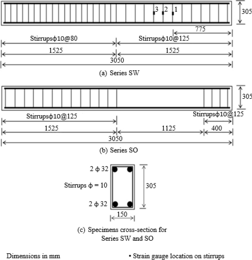
Figure 1. Detailing of the beams (Khalifa; Nanni, 2002).
| Material | Specifications | Compressive strength |
Yield stress |
Tensile strength |
Modulus of elasticity |
| Concrete | SW Series | 19.3 | - | 2.2 | 20 |
| SO Series | 27.5 | - | 2.7 | 25 | |
| Steel | φ = 32mm | - | 460 | 730 | 200 |
| φ = 10mm | - | 350 | 530 | 200 | |
| CFRP | t f = 0.165 mm | - | - | 3790 | 228 |
Khalifa (1999) divided each beam series into two groups depending on the relationship between the beam's shear span (a) and effective depth (d), using the a/d ratio equal to 3 and 4, which resulted in four groups of beams called SW3, SW4, SO3, and SO4. Regarding CFRP strengthening, one beam from each group was not strengthened with CFRP and was named SW3-1, SW4-1, SO3-1, and SO4-1. The remaining beams were reinforced with externally glued CFRP following three strengthening configurations, as shown in Figure 2, named SW3-2, SW4-2, SO3-2, SO3-3, SO3-4, SO3-5, SO4 -2 and SO4-3.
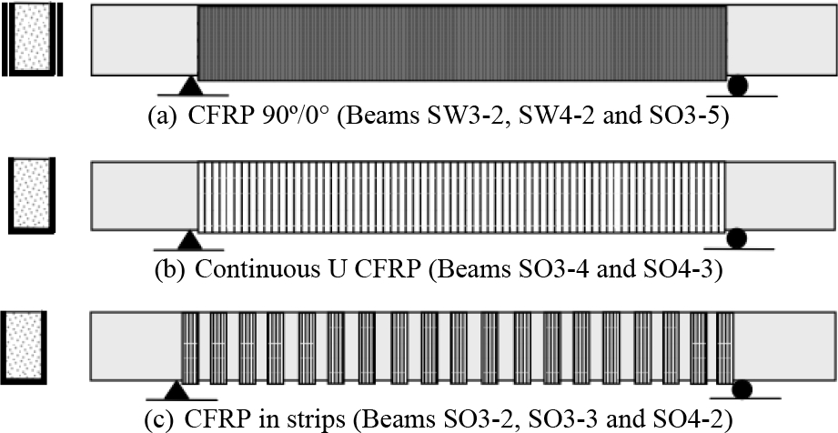
Figure 2. Schematic representation of strengthening configurations (Khalifa; Nanni, 2002).
Regarding loading, all beams were tested in four-point bending. For this purpose, a concentrated load was applied to a steel distribution beam to generate the two concentrated loads. For beams with an a/d ratio equal to 3, loads were applied 760 mm away from the supports, and for beams with an a/d ratio equal to 4 at a distance of 1020 mm. Four LVDTs (linear variable differential transformers) were used to monitor the vertical displacements at specific points of the beams. To carry out the numerical simulation of Khalifa's (1999) simply supported beams, only half the width of the beams was modeled, considering that the beams present symmetry in both geometry and loading along the cross-section. Plates were modeled with the SOLID186 element to avoid the stress concentration at the load application points and supports, with dimensions of 10x2x7.5 cm and an elastic modulus five times greater than concrete (E = 100,000 MPa).
Figure 3 presents the discretization of the mesh and all finite elements adopted in the beam model, where Figure 3a presents beam SO4-1, which is a beam without strengthening, Figure 3b shows beam SW3-2, which has continuous CFRP strengthening, and Figure 3c exposes beam SO4-2, strengthened with CFRP strips. In Figure 4, one can observe the discretization of the cross-section of the beams without strengthening, Figure 4a, and with CFRP strengthening, Figure 4b. The SOLID186 element and an elastic modulus of 2.5 GPa were adopted to model the adhesive used to glue the CFRP composite to the concrete surface. The adhesive was modeled in two layers, one on the concrete surface and the other on the surface of the CFRP composite, thus allowing the generation of the CONTA174 and TARGE170 elements between the adhesive layers. The CONTA174 contact element was generated in the adhesive layer connected to the CFRP strengthening, and the TARGE170 target element was generated in the adhesive layer in contact with the beam, Figure 5. As described in item 2 of this work, the properties of the interface model were obtained from the model and formulations proposed by Lu et al. (2005), thus making it possible to obtain the values of maximum bond stress, interface tangential stiffness and maximum slip, which are presented in Table 2.
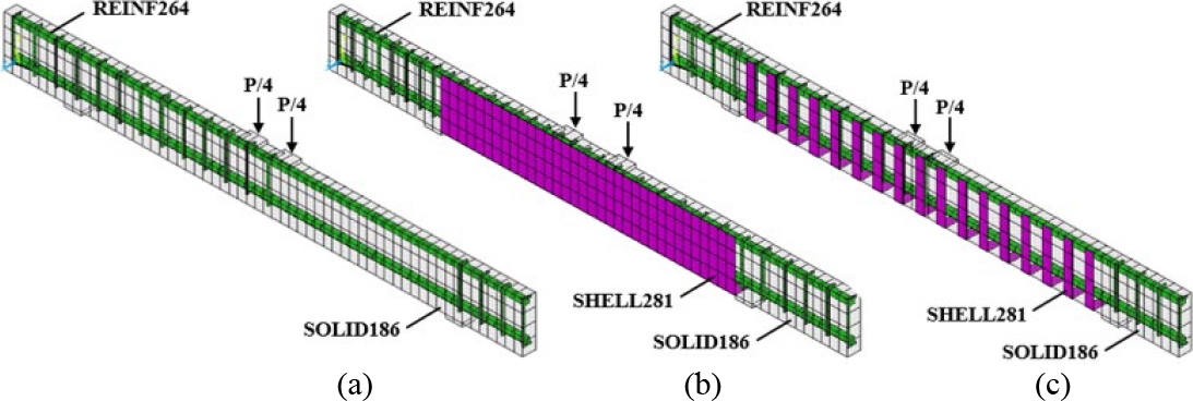
Figure 3. Finite element discretization of the beams: (a) SO4-1; (b) SW3-2, and (c) SO4-2.
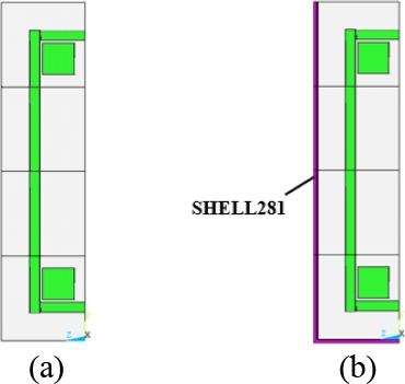
Figure 4. Cross-sections of the beams: (a) without strengthening; (b) U-shaped CFRP.
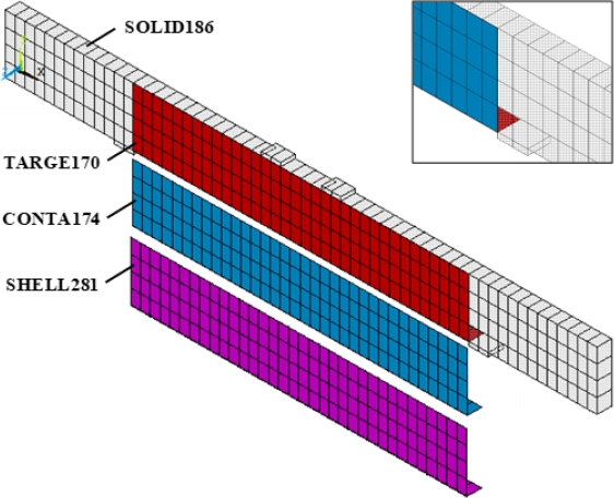
Figure 5. CONTA174 and TARGE170 elements in the SW3-2 beam model.
Table 2. Interface model parameters.
| Series | Maximum bond stress τf1 (kN/cm²) | Tangential stiffness Kt (kN/cm³) | Maximum slip s0 (cm) |
| SW | 0.317 | 77 | 0.0182 |
| SO | 0.366 | 77 | 0.0169 |
5. NUMERICAL RESULTS ANALYSIS
In this item, a comparative analysis is carried out between the numerical results and the experimental results obtained by Khalifa (1999), which were also addressed in the works of Khalifa, Belardi, and Nanni (2000) and Khalifa and Nanni (2002). To this end, the results are presented through load versus displacement curves in the shear span of interest and stresses in the concrete, reinforcement, and CFRP strengthening. The behavior of the interface was also analyzed using the bond stress and slip results obtained by the contact elements. To simulate the loading used in the experimental test, a vertical displacement was imposed at the points where the concentrated loads acted, the adopted value being at least 50% greater than that observed in the experimental test. Considering the number of results obtained for the twelve simulated beams, it was decided to present the results of three beams, one for each identified failure mode, as well as a summary of the results of all beams tested, as shown in Table 3. It is important to highlight that a complete analysis of the results of all beams can be found in the work of Soares (2022).
| No. | Beam Description | Shear strengthening with CFRP | Experimental | Numerical | Variation |
||
| Failure mode | Load |
Failure mode | Load |
||||
| 1 | SW3-1 | - | Shear | 252.8 | Shear | 249.9 | -1.1 |
| 2 | SW3-2 | Two plies (90°/0°) | Splitting | 354.6 | Splitting | 355.3 | 0.2 |
| 3 | SW4-1 | - | Shear | 201.2 | Shear | 231.6 | 15.1 |
| 4 | SW4-2 | Two plies (90°/0°) | Splitting | 361.6 | Splitting | 372.8 | 3.1 |
| 5 | SO3-1 | - | Shear | 151 | Shear | 151 | 0.0 |
| 6 | SO3-2 | U-strips, 50 @ 125mm | Debonding | 261.9 | Debonding | 235 | -10.3 |
| 7 | SO3-3 | U-strips, 75 @ 125mm | Debonding | 267.1 | Debonding | 240.4 | -10.0 |
| 8 | SO3-4 | One ply 90o | Debonding | 289 | Debonding | 337.1 | 16.6 |
| 9 | SO3-5 | Two plies (90°/0°) | Splitting | 339.4 | Splitting | 321.2 | -5.4 |
| 10 | SO4-1 | - | Shear | 129.4 | Shear | 126.3 | -2.4 |
| 11 | SO4-2 | U-strips, 50 @ 125mm | Debonding | 254.9 | Debonding | 240.5 | -5.6 |
| 12 | SO4-3 | U-strips, 50 @ 125mm | Splitting | 311.1 | Splitting | 341.5 | 9.8 |
Figure 6 presents the load-displacement results, experimental tests, and numerical analyses of beams SW3-1 and SW3-2. From the analysis of these results, it was verified that the numerical simulation represents very well the behavior of the two beams analyzed since the curves obtained numerically have a maximum load equal to the curves obtained in the experimental tests. Regarding the failure mode of these beams, it was possible to verify, through computational analysis, that beam SW3-1 fails due to shear, as the stirrups reach the maximum yield stress (35 kN/cm²) before starting the yield process. of the longitudinal reinforcement (46 kN/cm²), as shown in Figure 7. In beam SW3-2, the stress in the concrete in the z-direction, Figure 8, presents a value much higher than the value of the concrete's tensile strength (0.22 kN/cm²), thus showing that the beam rupture occurred due to concrete failure. The failure mode of beams SW3-1 and SW3-2 follows that observed by Khalifa (1999) in experimental tests, as it was found that the failure of beam SW3-1 occurred due to shear, as shown in Figure 13a, and beam SW3-2 caused cracking of the concrete, as shown in Figure 13b.
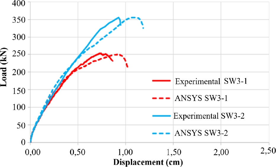
Figure 6. Load-displacement diagram of beams in group SW3.

Figure 7. Stress in the reinforcement of beam SW3-1 (kN/cm²).
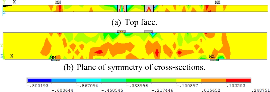
Figure 8. Stress in the concrete of beam SW3-2 (kN/cm²).
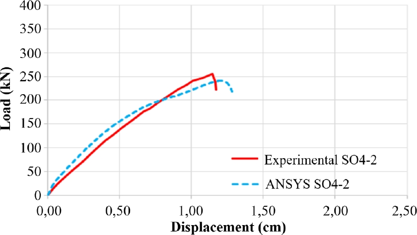
Figure 9. Load-displacement diagram of beam SO4-2.
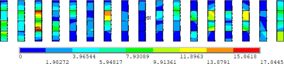
Figure 10. Principal stress in the CFRP reinforcement of beam SO4-2 (kN/cm²).
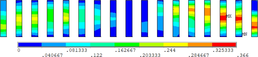
Figure 11. Bond stresses at the SO4-2 beam interface (kN/cm²).
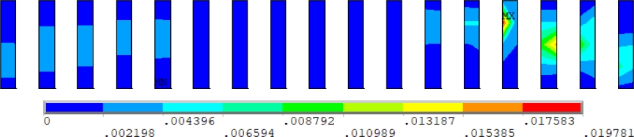
Figure 12. Bond-slip at the SO4-2 beam interface (cm).
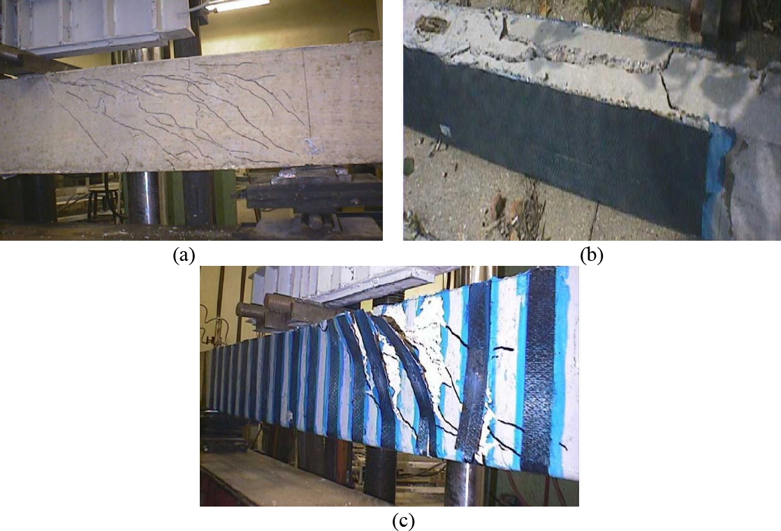
Figure 13. Experimental failure mode of the beams: (a) SW3-1; (b) SW3-2, and (c) SO4-2 (Khalifa, 1999).
Figure 9 presents the load-displacement results for the numerical simulation and the experimental test of beam SO4-2, which is strengthened with CFRP in 50 mm strips. It is possible to observe that the curve obtained numerically is, initially, more rigid than the experimental curve. However, from a load of approximately 150 kN, there is a reduction in this stiffness, and the curve presents a maximum numerical load that is very close to the load observed experimentally. Checking the stress results in the CFRP strengthening, Figure 10, as well as the bond stress and slip at the concrete-strengthening interface, Figure 11 and Figure 12, it was found that this reduction in the stiffness of the load-displacement curve occurred due to the debonding of the strengthening in the shear span of interest, since the interface reached the maximum adhesion stress (0.366 kN/cm²) and the maximum slip (0.0169 cm), thus reproducing the behavior observed in the experimental test carried out by Khalifa (1999), as shown in Figure 13c.
Table 3 presents the type of strengthening of each simulated beam, the numerical and experimental results of failure mode and ultimate load, and the variation of this load. From the analysis of these results, it was verified that the numerical simulations were able to identify the same rupture mode observed in the experimental test. Furthermore, it was found that the numerical values of the ultimate load are close to those observed by Khalifa (1999) experimentally since nine beams presented a variation in the ultimate load of up to 10% and three beams a slightly higher value, with a maximum variation of 16.6%.
From the results of the numerical simulations, it was found that beams SW3-1, SW4-1, SO3-1, and SO4-1, which do not have CFRP strengthening, failed due to shear, following what was observed experimentally since the beams by Khalifa (1999) were designed to induce this shear failure. Furthermore, it was verified in the simulations that beams SW3-2, SW4-2, SO3-5, and SO4-3, all strengthened with CFRP, did not show a loss of contact between the interface elements. That is, the strengthening did not debond, and it was observed that the rupture occurred due to failure in the concrete that reached strains higher than their limit value. These results align with the behavior observed in the experimental tests by Khalifa (1999), which found the failure of these structural elements due to the concrete splitting.
In cases where the failure of the beam in the experimental test occurred due to strengthening debonding, two distinct behaviors were observed in the numerical simulation. The first was verified in beams with CFRP strengthening in strips (SO3-2, SO3-3, and SO4-2), where the interface reaches the maximum bond stress and, subsequently, the maximum slip in the span of interest (between the second point load and the second support), causing a reduction in the stiffness of the load versus displacement curve at the moment of the strengthening debonding on the right side. Furthermore, at this moment, the CFRP strengthening reaches the highest stress value in the shear span. After this, the stress begins to decrease in the strengthening on the right side and, subsequently, starts to present a maximum value in the strips located on the left side until the beam reaches the ultimate load. The second behavior was observed in the beam with continuous strengthening (SO3-4), where the interface reaches the maximum sliding value for the numerical failure load, indicating that the beam failure occurred at the moment of the strengthening debonding in the shear span.
6. CONCLUSIONS
The main objective of the present work was to demonstrate the application of a computational model to simulate the behavior of simply supported reinforced concrete beams, without and with shear strengthening with CFRP, using the finite element method (FEM) and ANSYS software customized for this purpose. The conclusions are summarized below:
It was verified that the nonlinear structural models proposed in this work could predict with reasonable accuracy the behavior of the simulated beams, both in terms of load-displacement and the load and failure mode of the beams.
The simulations could predict the different beam failure modes observed experimentally: shear failures, concrete splitting, and strengthening debonding situations.
The visual post-processing resources of ANSYS enabled the analysis of stress distribution in concrete, steel, and CFRP strengthening, as well as the evaluation of bond stresses and slips at the concrete-strengthening interface.
7. ACKNOWLEDGMENTS
The authors would like to thank CAPES - Coordination for the Improvement of Higher Education Personnel and CNPq - National Council for Scientific and Technological Development for supporting this study.
8. REFERENCES
ANSYS, Inc. (2021), ANSYS Help System, version 19.2.
Fédération Internationale du Betón (2013), fib Model Code for Concrete Structures 2010. 434 p.
Hoffman, I. S., Lazzari, B. M., Campos, A., Lazzari, P. M., Pacheco, A. R. (2022), Finite element numerical simulation of a cable-stayed bridge construction through the progressive cantilever method. Structural Concrete, v. 23 (2), p. 632-651. https://doi.org/10.1002/suco.202100662
Khalifa, A. (1999), Shear performance of reinforced concrete beams strengthened with advanced composites. 175 p. PhD Thesis, Structural Engineering Department, Alexandria University, Egypt.
Khalifa, A., Belarbi, A., Nanni, A. (2000), Shear Performance of RC Members Strengthened with Externally Bonded FRP Wraps, Proc., 12th World Conference on Earthquake Engineering, Jan 30- Feb 04, Auckland, New Zealand, paper 305,10 p.
Khalifa, A., Nanni, A. (2002), Rehabilitation of rectangular simply supported RC beams with shear deficiencies using CFRP composites. Construction and Building Materials, v. 16, n. 3, p. 135-146. https://doi.org/10.1016/S0950-0618(02)00002-8
Lazzari, B. M., Campos Filho, A., Lazzari, P. M., Pacheco, A. R. (2017a), Using element-embedded rebar model in ANSYS for the study of reinforced and prestressed concrete structures. Computers and Concrete, v. 19, p. 347-356. https://doi.org/10.12989/cac.2017.19.4.347
Lazzari, P. M., Campos Filho, A., Lazzari, B. M., Pacheco, A. R. (2017b), Structural analysis of a prestressed segmented girder using contact elements in ANSYS. Computers and Concrete, v. 20, p. 319-327. https://doi.org/10.12989/cac.2017.20.3.319
Lazzari, P. M., Campos Filho, A., Lazzari, B. M., Pacheco, A. R., Gomes, R. (2019), Numerical simulation of the constructive steps of a cable-stayed bridge using ANSYS. Structural Engineering and Mechanics, v. 69, p. 269-281. https://doi.org/10.12989/sem.2019.69.3.269
Machado, G. G., Campos Filho, A., Lazzari, P. M., Lazzari, B. M., Pacheco, A. R. (2023), Numerical simulation by the finite element method of the constructive steps of a precast prestressed segmental bridge. Structural Engineering and Mechanics, v. 85, n. 2, p. 163-177. https://doi.org/10.12989/sem.2023.85.2.163
Medeiros, M. V. (2019), Simulação numérica do comportamento de peças fletidas reforçadas com PRFC. 194 p. Dissertação (Mestrado em Engenharia Civil) - Programa de Pós-Graduação em Engenharia Civil. Universidade Federal do Rio Grande do Sul, Porto Alegre.
Mhanna, H. H., Hawileh, R. A., Abdalla, J. A. (2021), Shear behavior of RC T-beams externally strengthened with anchored high modulus carbon fiber-reinforced polymer (CFRP) laminates. Composite Structures, v. 272, p. 114198. https://doi.org/10.1016/j.compstruct.2021.114198
Ouyang, Z., Li, G. (2009), Cohesive zone model based analytical solutions for adhesively bonded pipe joints under torsional loading. International Journal of Solids and Structures, v. 46, n. 5, p. 1205-1217. https://doi.org/10.1016/j.ijsolstr.2008.10.021
Sarturi, F. D. M. (2014), Simulação computacional de estruturas de concreto reforçadas com aço e compósitos de fibra de carbono. 234 p. Dissertação (Mestrado em Mecânica Computacional) - Programa de Pós-Graduação em Métodos Numéricos em Engenharia. Universidade Federal do Paraná, Curitiba.
Soares, P. B. (2022), Simulação através do Método dos Elementos Finitos do reforço ao esforço cortante de vigas de concreto utilizando polímeros reforçados com fibras de carbono. 215 p. Dissertação (Mestrado em Engenharia Civil) - Programa de Pós- Graduação em Engenharia Civil. Universidade Federal do Rio Grande do Sul, Porto Alegre.
Soares, P. B., Lazzari, P. M., Campos Filho, A., Lazzari, B. M., Pacheco, A. R. (2023), Identification of the failure modes of CFRP shear-strengthened reinforced concrete beams by the finite element method. IBRACON Structures and Materials Journal, v. 16, n. 3, p. 1-21. https://doi.org/10.1590/S1983-41952023000300004
Titello, E. P. (2020), Análise da confiabilidade de vigas em concreto armado reforçado com fibras de aço em relação aos esforços transversais. 161 p. Dissertação (Mestrado em Engenharia Civil) - Programa de Pós- Graduação em Engenharia Civil. Universidade Federal do Rio Grande do Sul, Porto Alegre.